
 ID
Fast delivery
The catalogue states a transport speed of 3–8 metres per second for material deliveries, including urgent requirements.
Point-to-point delivery, powered by air.
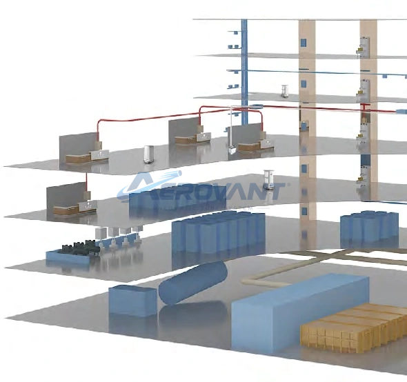
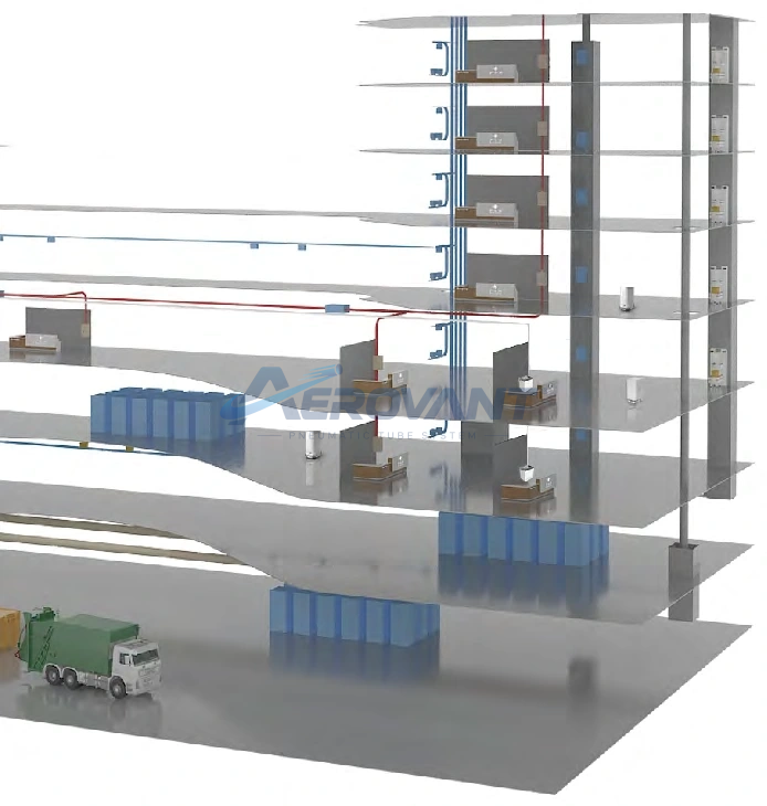
The pneumatic tube system moves material carriers through a pipe network using compressed air. Sending and receiving stations are connected by an automatically controlled network, enabling point-to-point deliveries to suit hospital requirements.
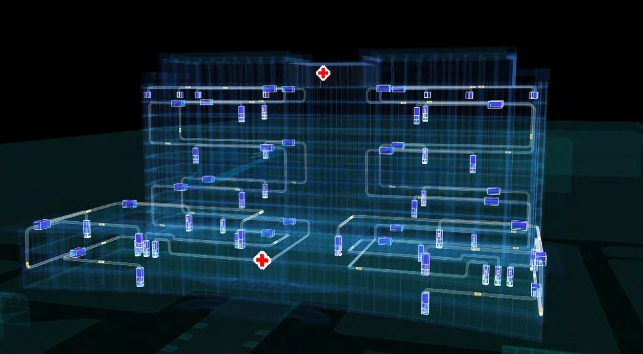
Solution overview
Electromechanical and microcomputer controls manage carrier movement. Network management and monitoring computers help operators view deliveries, track status, and address faults.
The network can be designed around each department's requirements. The catalogue includes outpatient services, emergency departments, nurse stations, laboratories, pharmacies, transfusion services, pathology, ICU, CCU, and operating rooms. Each load type must meet its handling requirements.
Features & benefits
The catalogue states a transport speed of 3–8 metres per second for material deliveries, including urgent requirements.
Installation is described as suitable for both new and operating hospitals. Routes and network expansion depend on building conditions.
Dynamic process displays, real-time recording, saved records, printing, fault codes, and remote online diagnostics support operational oversight.
The catalogue presents pneumatic transport as an option for multiple departments with relatively modest installation and maintenance requirements. Actual costs depend on the project design.
How it works
Place suitable materials inside the carrier, then close both ends.
The operator uses the station panel to initiate delivery to the selected point.
The central controller selects the route. Air pressure and suction move the carrier through pipes and diverters.
The carrier arrives at the receiving station. Operators can monitor the process and records through the control system.
System components
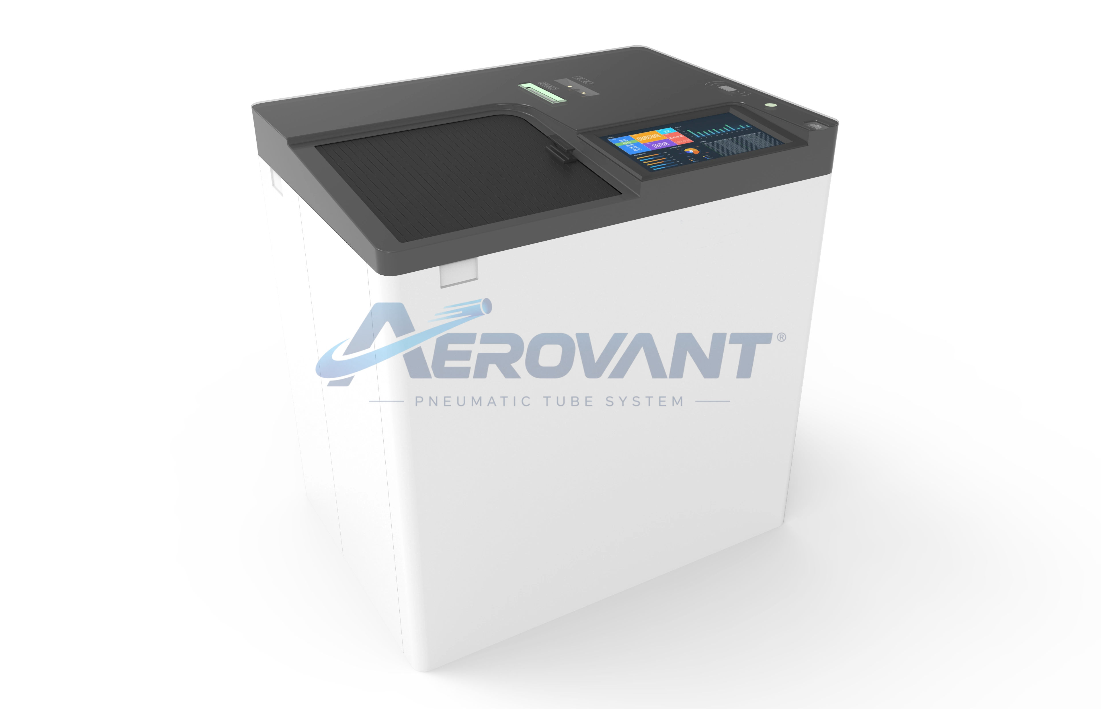
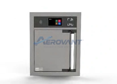
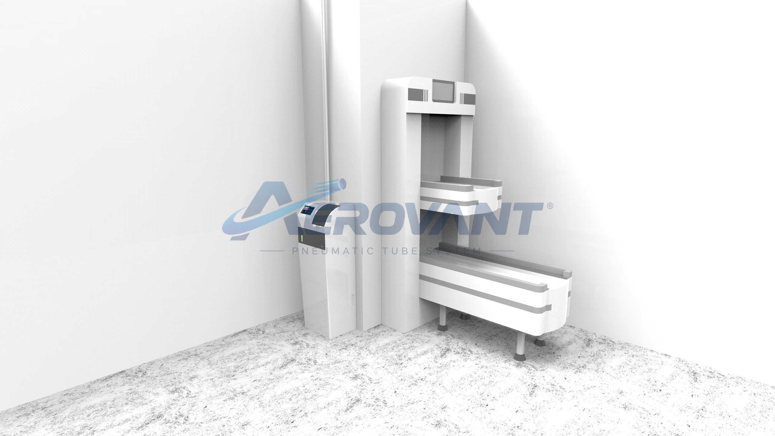
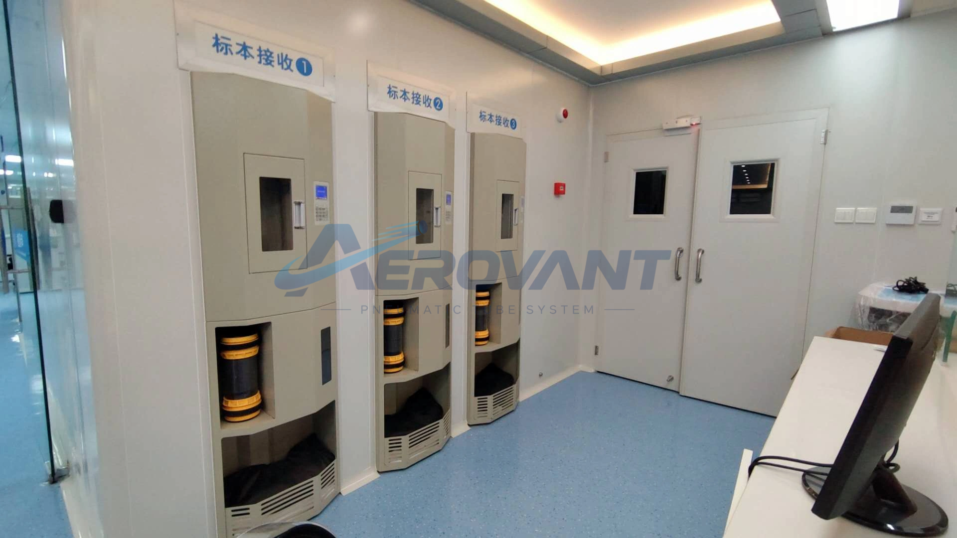
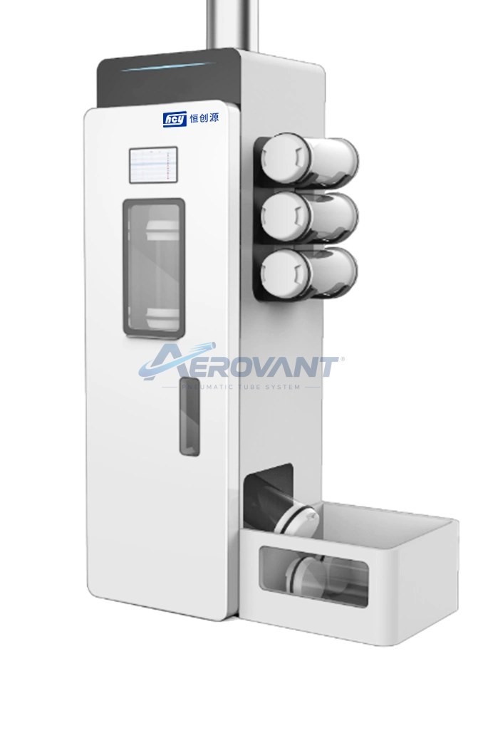
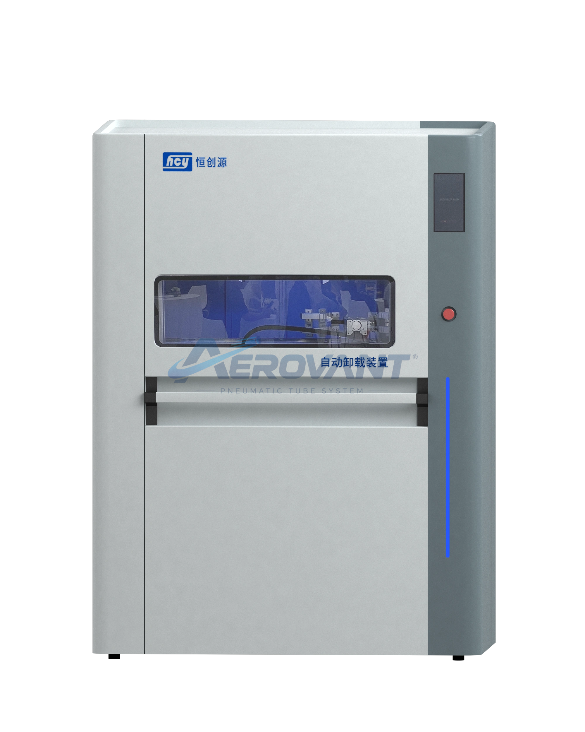
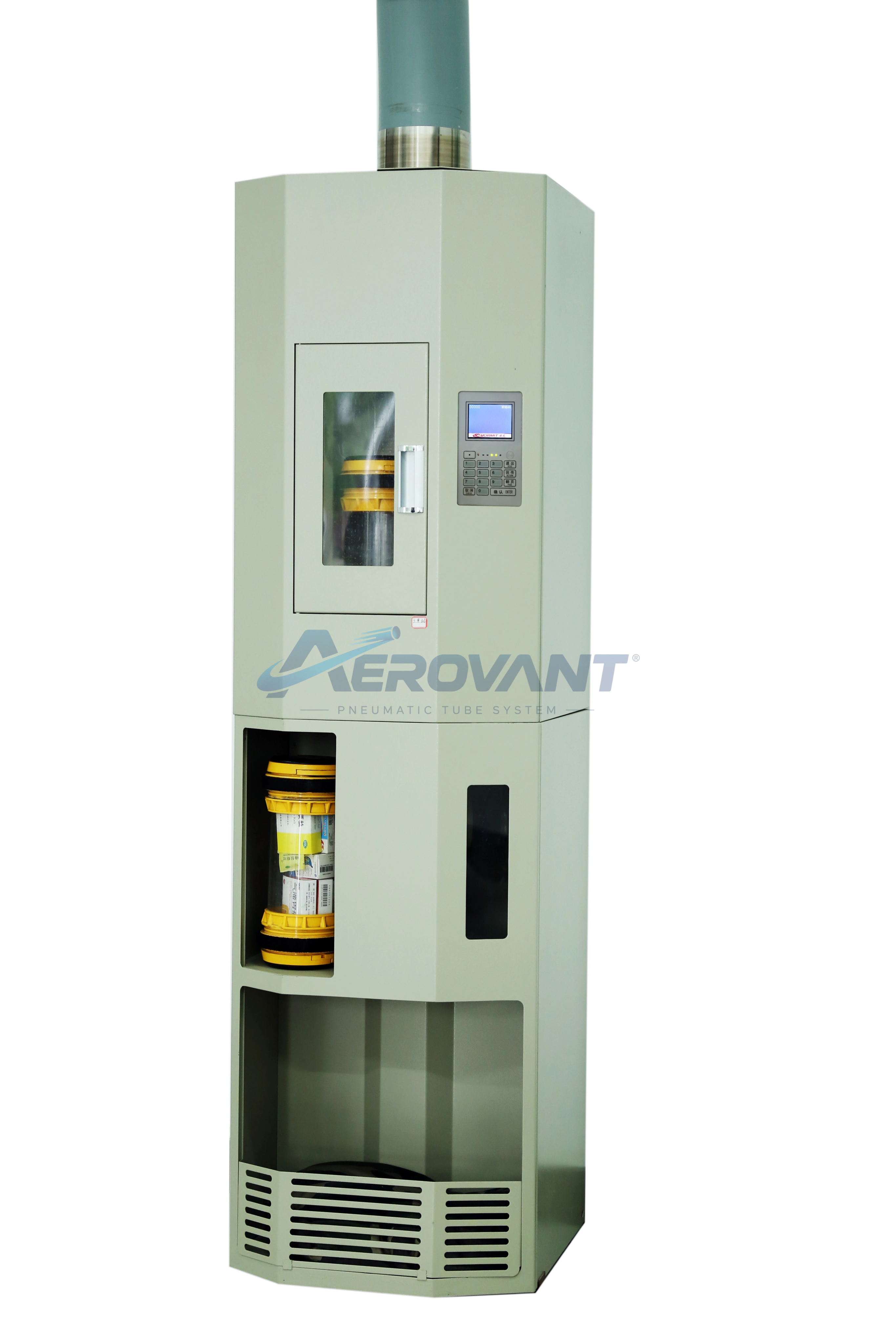
The operating panel and LCD dynamically display working status. Painted steel construction and a sound-insulating layer support installation in care areas.
 Enlarge ↗
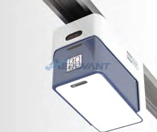
Alternative station designs; model selection and placement depend on facility requirements.
 Enlarge ↗
Alternative station designs; model selection and placement depend on facility requirements.
 Enlarge ↗
Alternative station designs; model selection and placement depend on facility requirements.
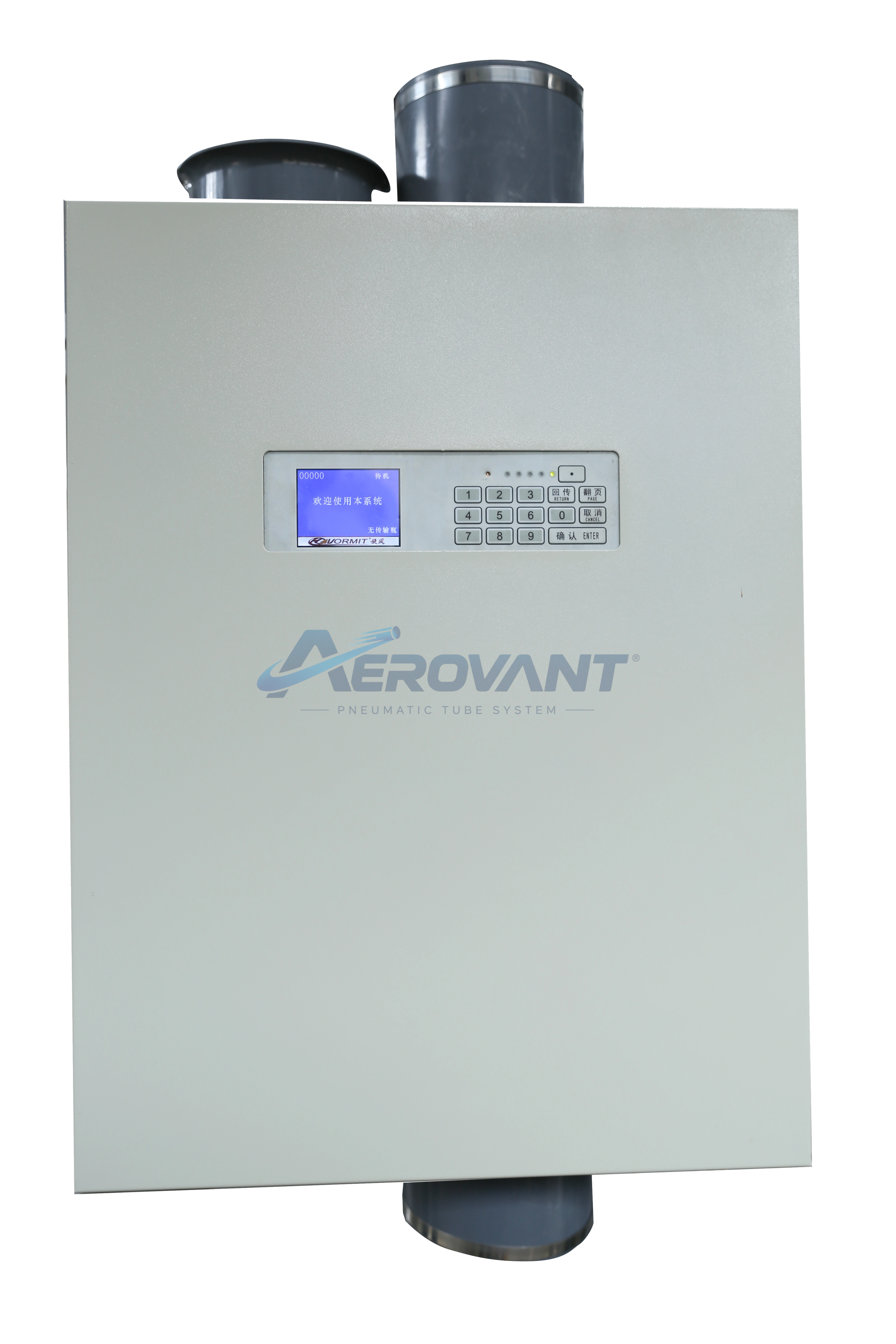 Enlarge ↗
Alternative station designs; model selection and placement depend on facility requirements.
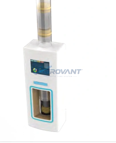 Enlarge ↗
Alternative station designs; model selection and placement depend on facility requirements.
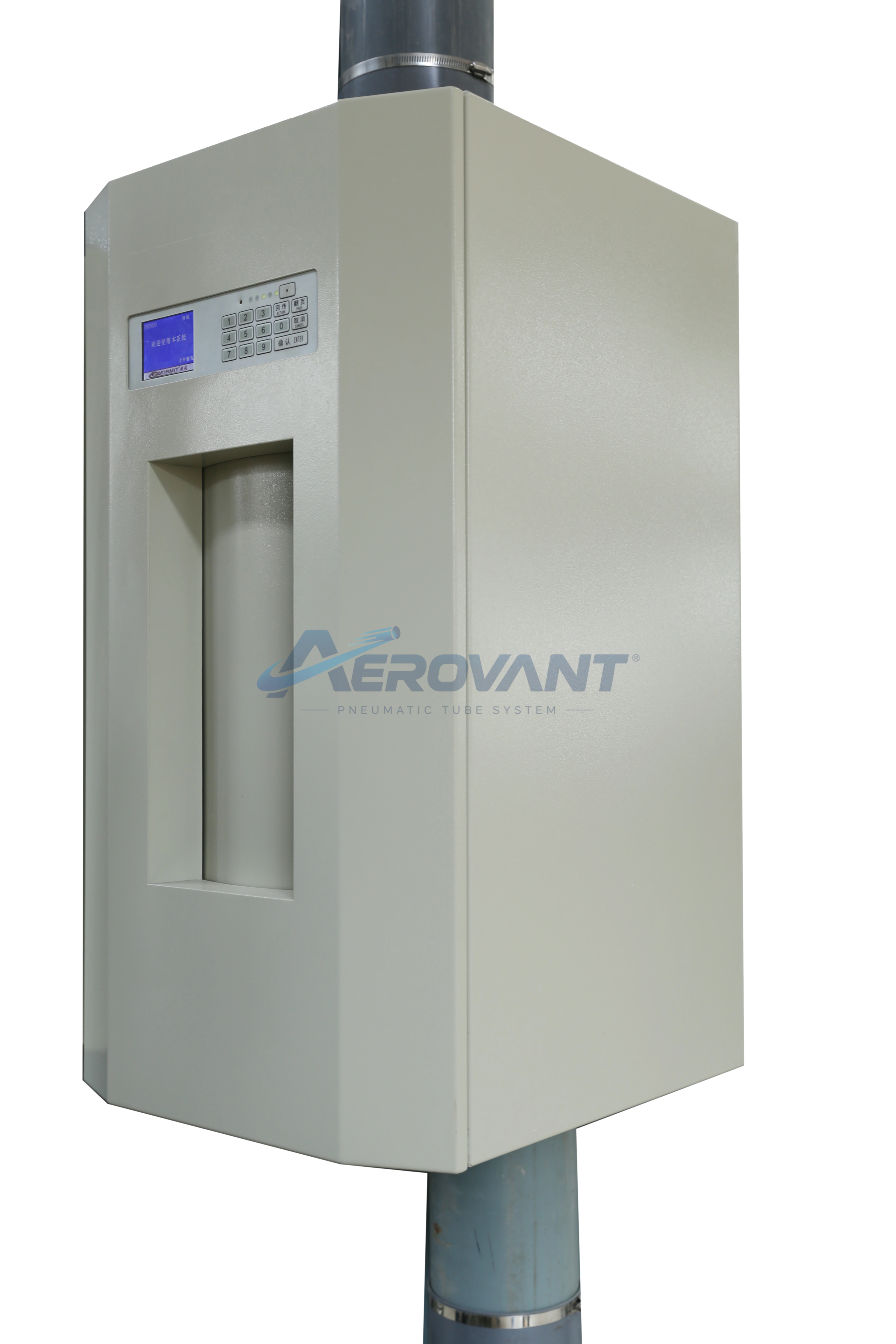 Enlarge ↗
Alternative station designs; model selection and placement depend on facility requirements.
Includes a central controller, branch controllers, and PC monitoring equipment. Supports Chinese and English interfaces, saved records, fault code analysis, and remote diagnostics.
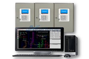 Enlarge ↗
Network control and monitoring equipment.
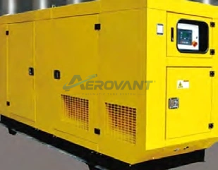
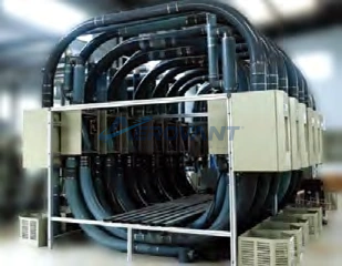
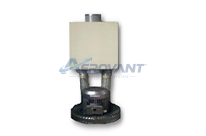
A compressor and commutator produce positive or negative air pressure. Reversing airflow moves the carrier through the network.
 Enlarge ↗
Equipment that drives airflow in the pneumatic system.
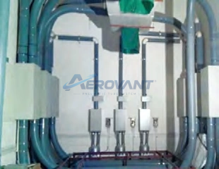
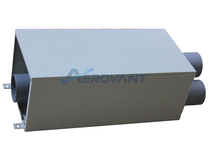
A three-way diverter selects a port as directed by the central controller. The catalogue lists antistatic equipment and precise angle sensors to support positioning.
 Enlarge ↗
Route selection equipment directing carriers to the destination station.
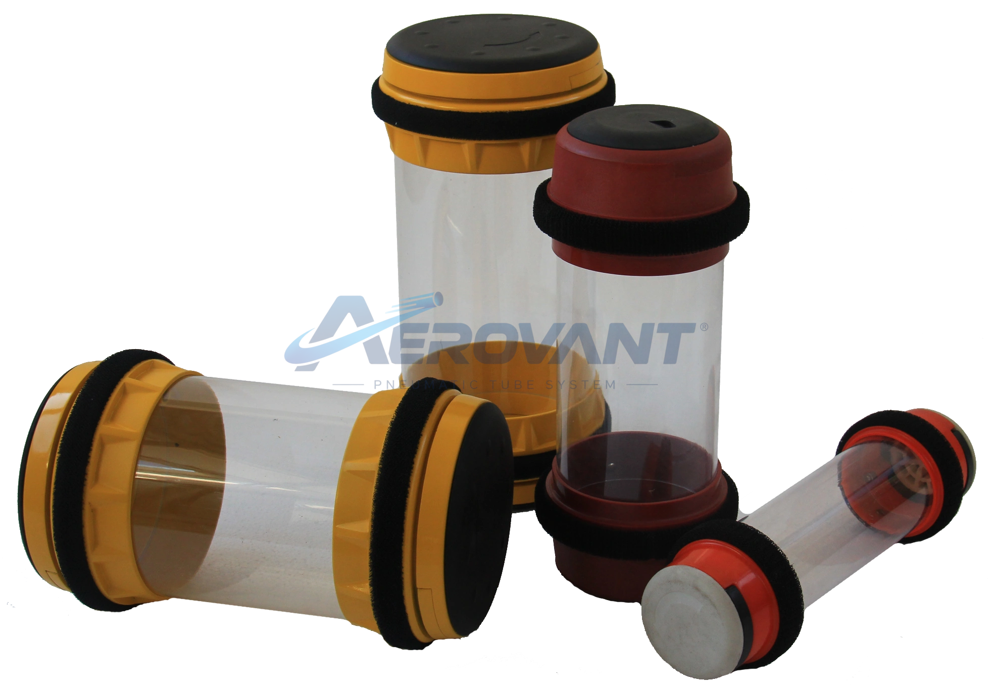
A cylindrical container with double screw caps and RFID chips at both ends to support carrier identification.
 Enlarge ↗
A delivery container with double caps and RFID identification.
Network configuration
The network can use dual-line, rotary, or multi-line switching configurations. Selection depends on the station layout and required delivery routes.
Specifications & configuration
The following technical parameters provide an initial guide. Final configuration depends on facility requirements and site conditions.
| Parameter | Details |
|---|---|
| Drive power | Compressed air; positive/negative pressure control |
| Transport speed | 3–8 m/s, according to the catalogue |
| Control | Central and branch control with PC monitoring |
| Central control interface | Chinese and English |
| Carrier | Cylindrical, double screw caps, RFID at both ends |
| Route selection | Three-way diverter, angle sensors, antistatic equipment |
The hospitals in the applications section are manufacturer catalogue references, not claims about Aerovant's project portfolio. Speed and configuration require confirmation during design.
Applications
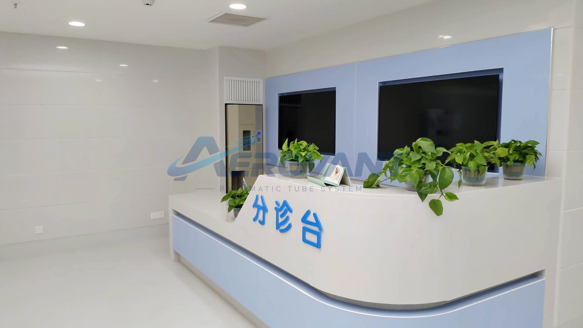
Application areas can be selected to suit the facility's internal transport requirements.
Product photographs and diagrams are based on the manufacturer's technical materials.
The Aerovant Ecosystem
Let's get connected
Start by identifying your facility's internal transport requirements.