

 ID
Aerovant Gallery
Device & System Gallery.
Explore equipment options, product details, and installation examples in one gallery.
Equipment Gallery
Equipment & system renderings
Equipment renderings, carriers, conveyors, robots, diagrams, and system views from the supplied product assets.
 Enlarge ↗
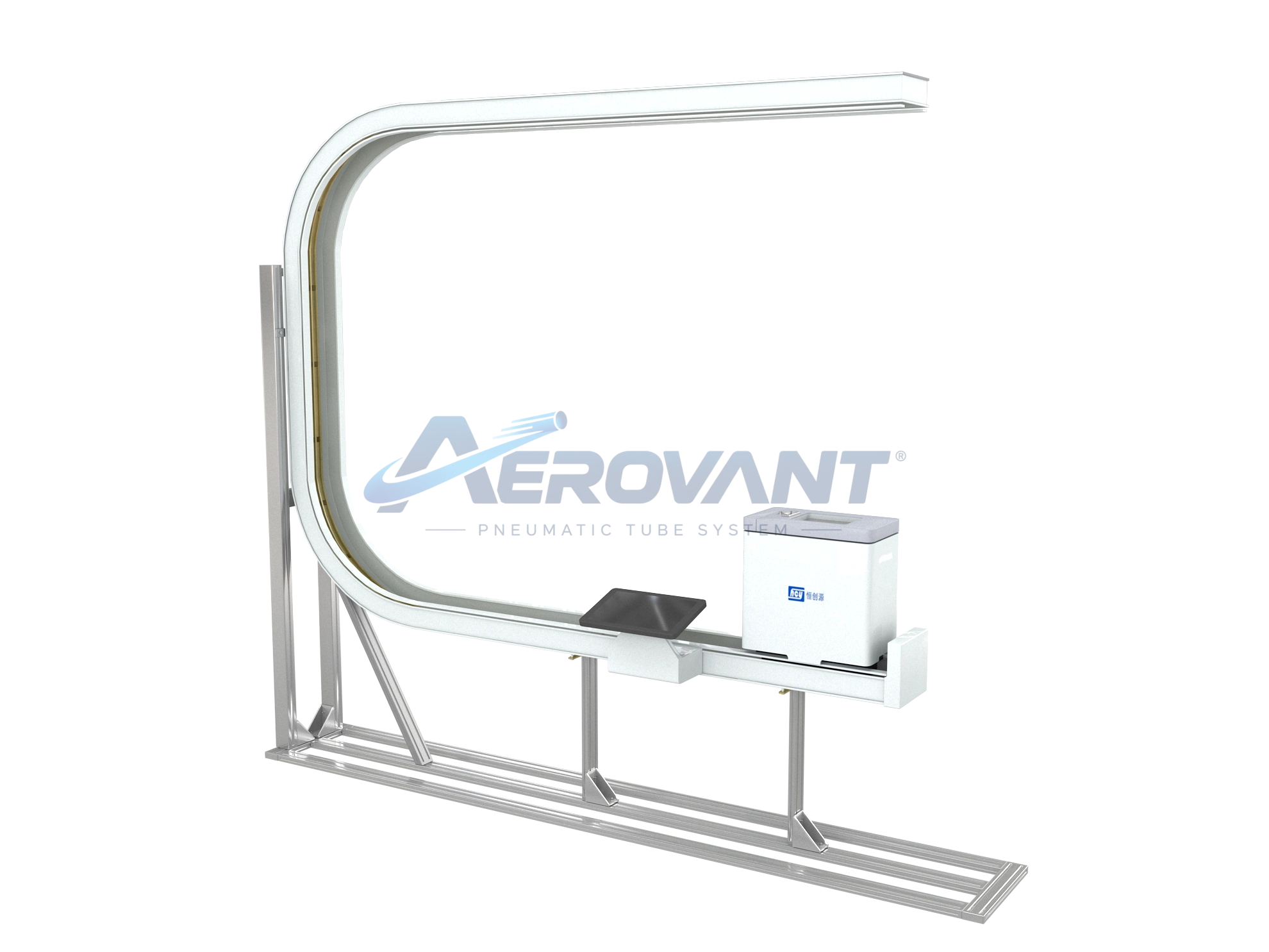
Rendering of a transport line and service terminal.
 Enlarge ↗
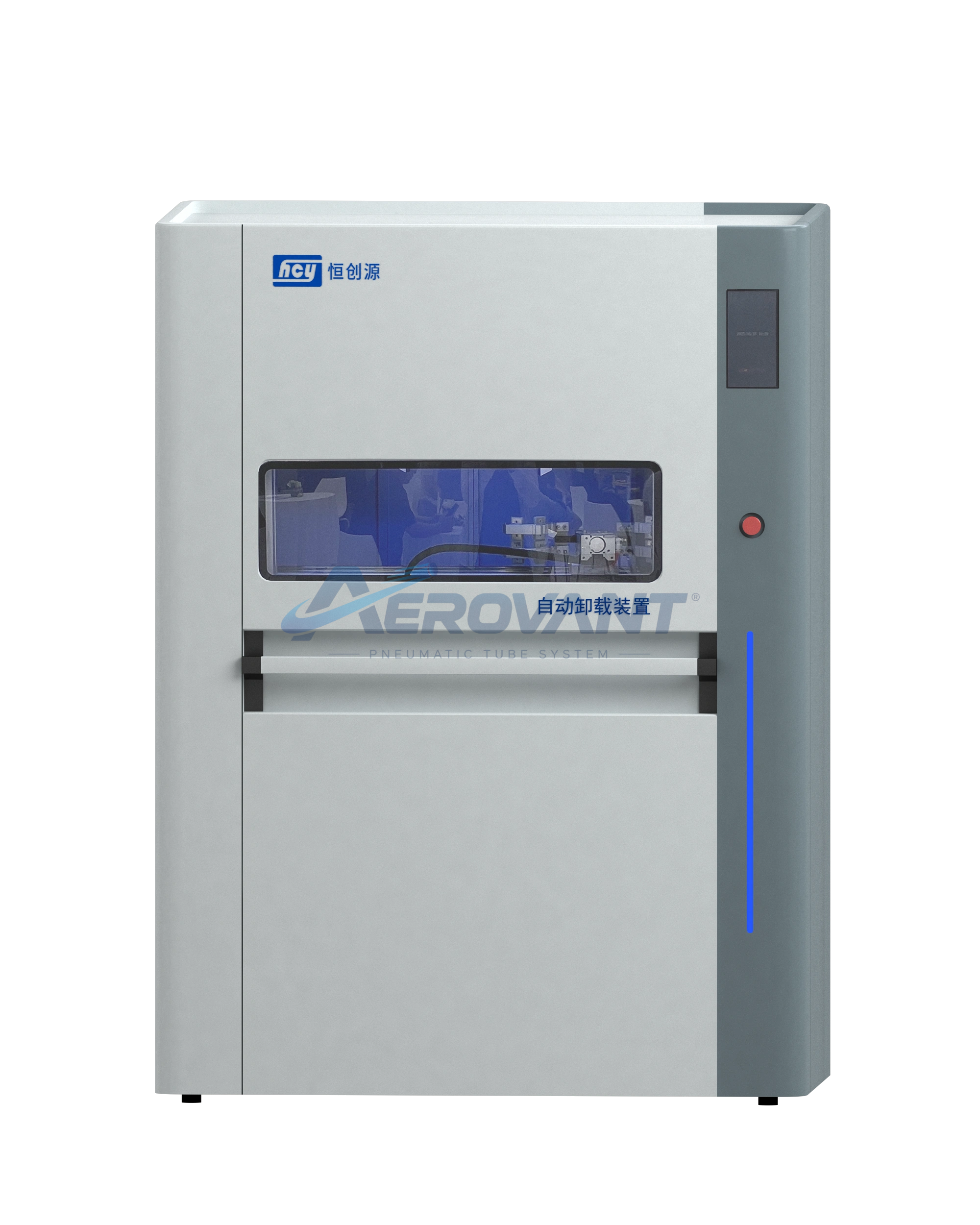
Front view of a station with its control panel.
 Enlarge ↗
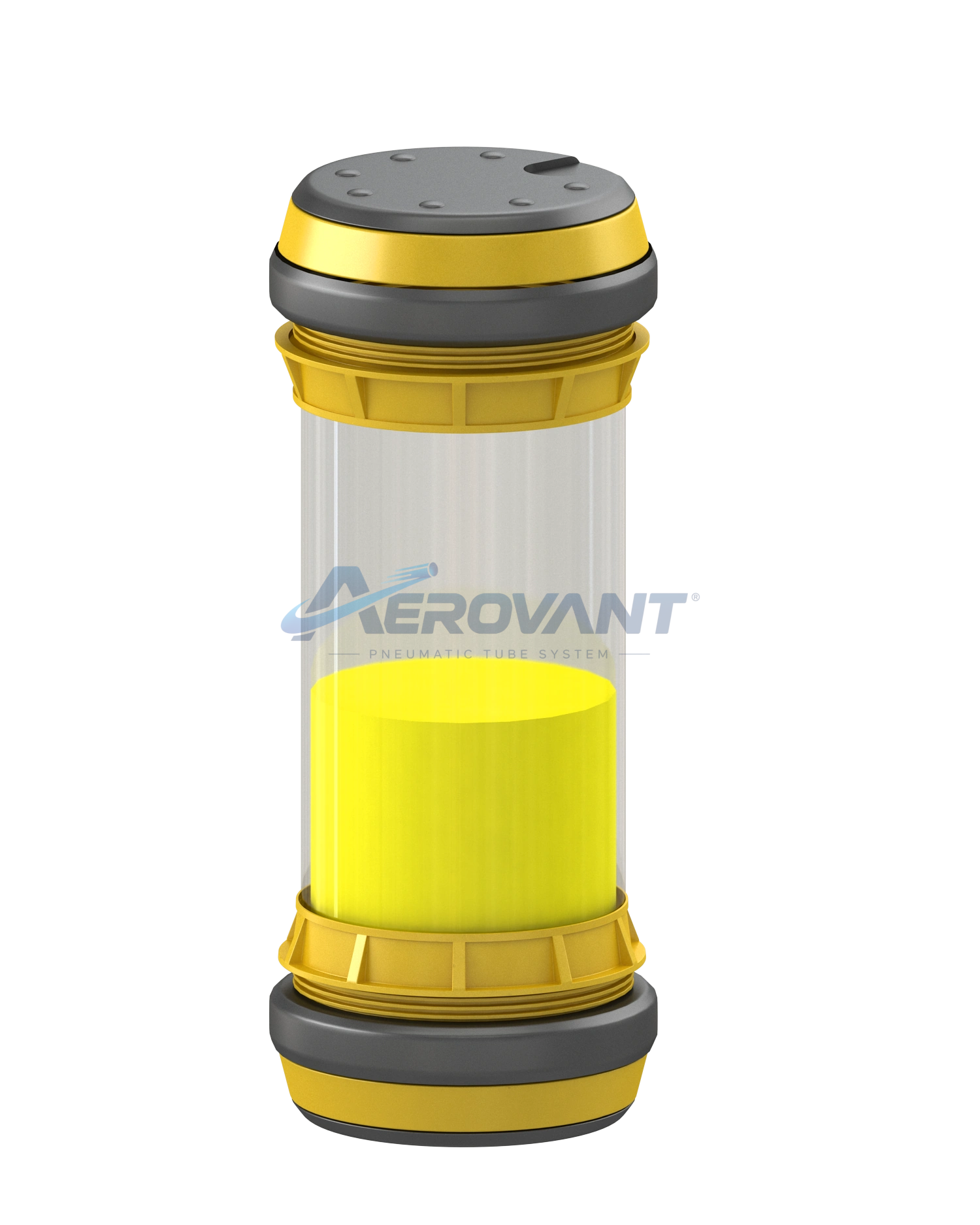
Rendering of a cylindrical transport container.
 Enlarge ↗
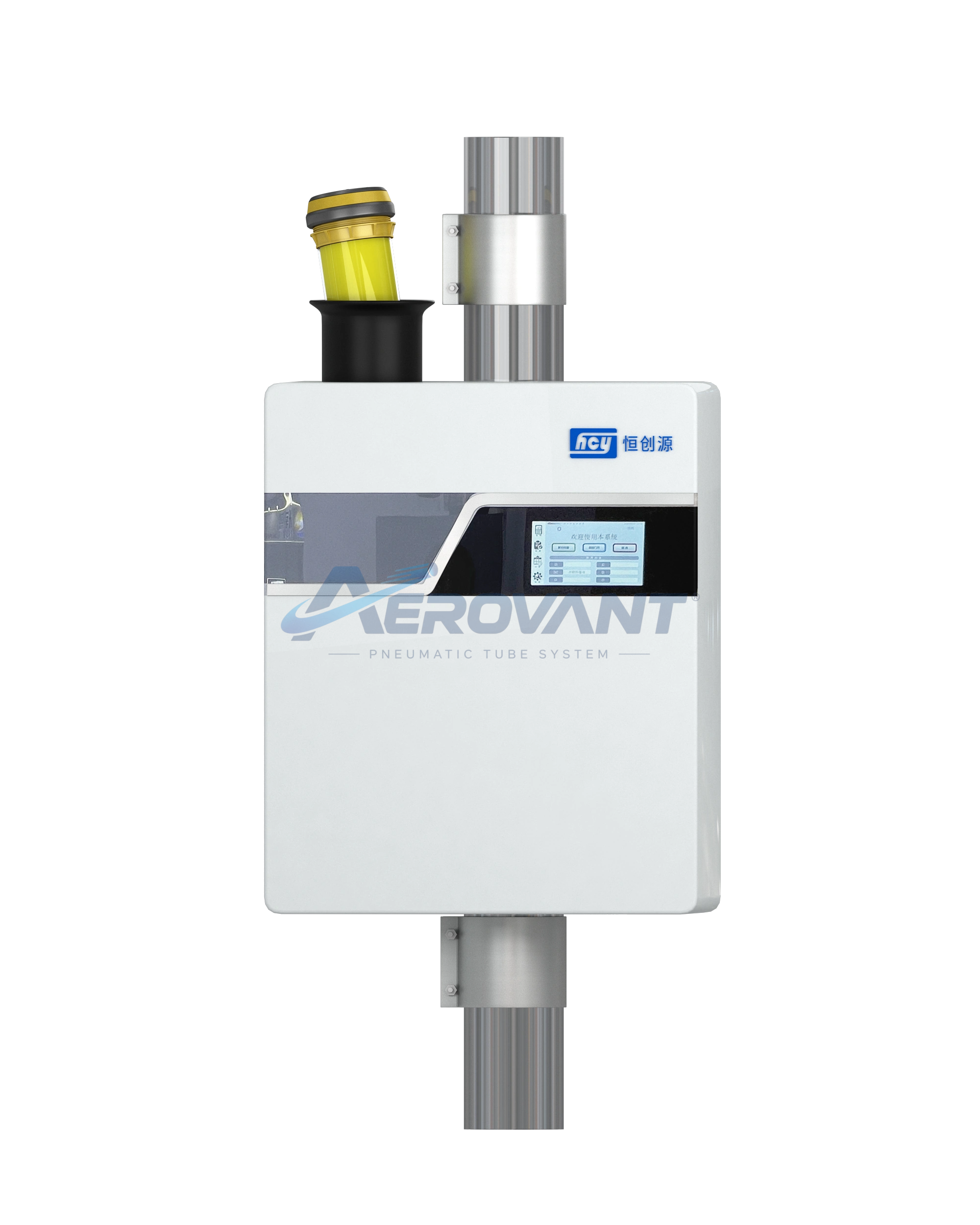
Rendering of a terminal with connections at the top.
 Enlarge ↗
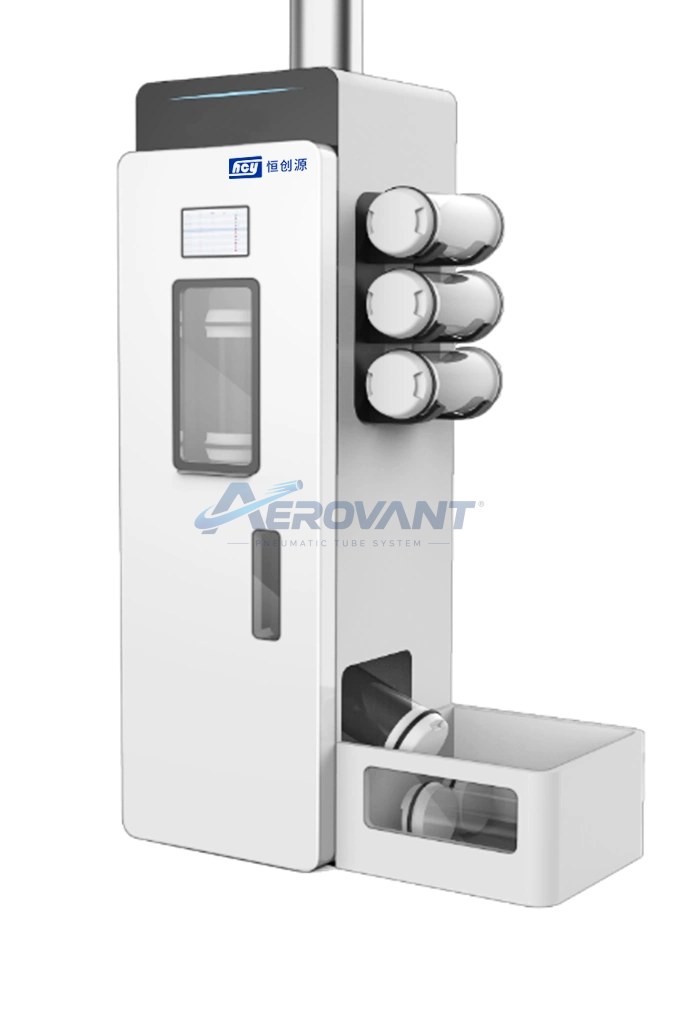
Station equipment with carrier storage along the side.
 Enlarge ↗
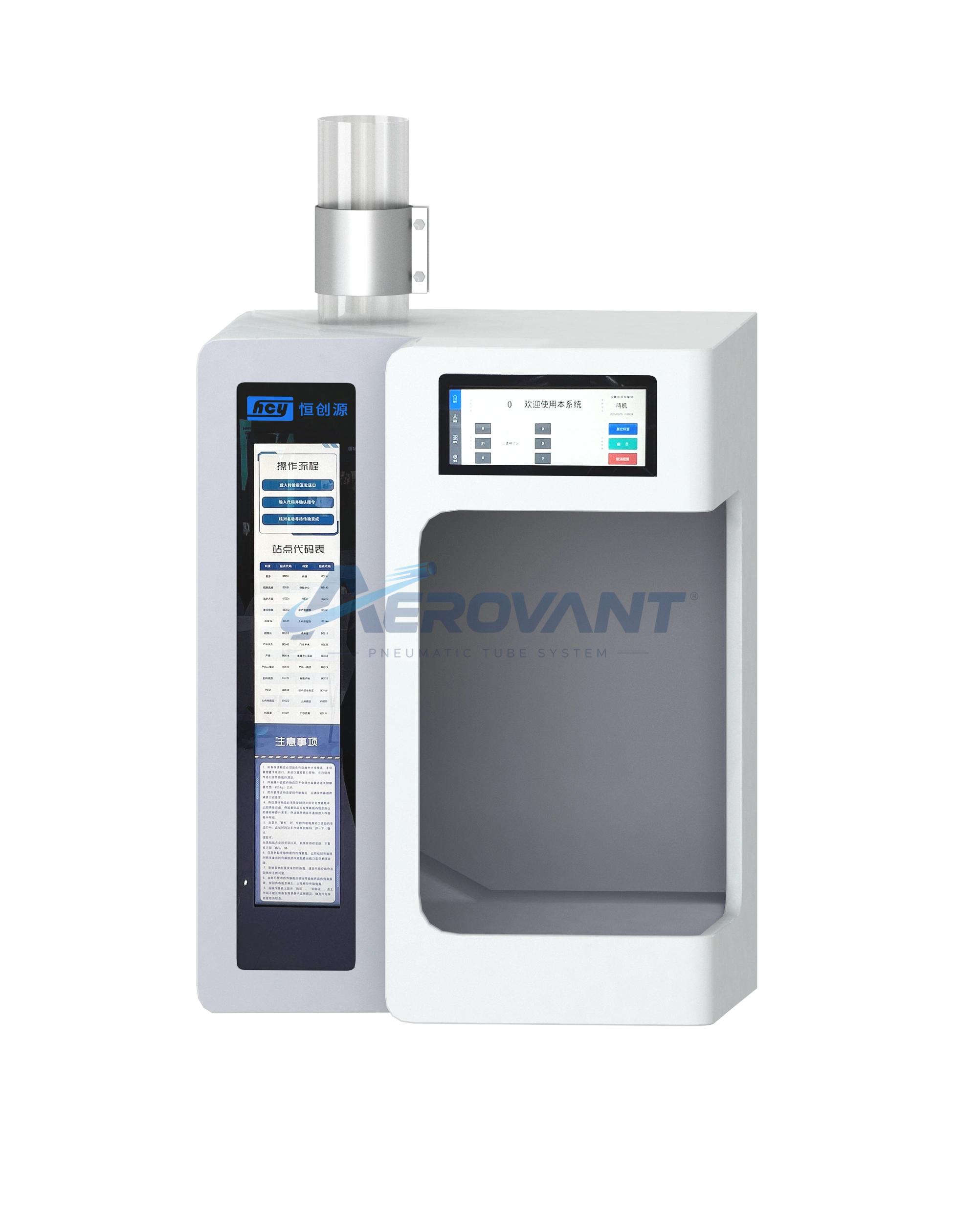
Rendering of a terminal and its access area.
 Enlarge ↗
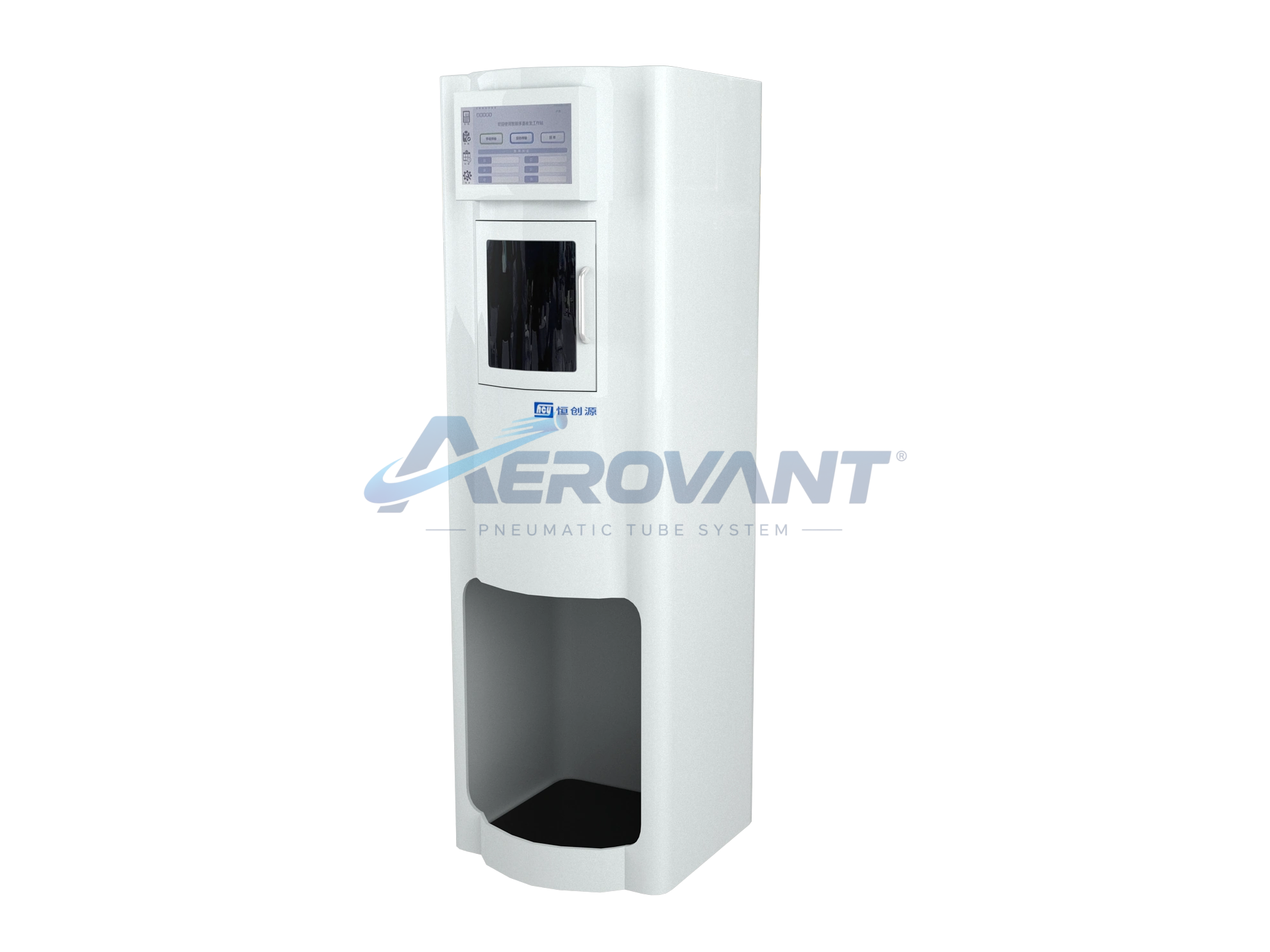
View of a vertical terminal unit.
 Enlarge ↗
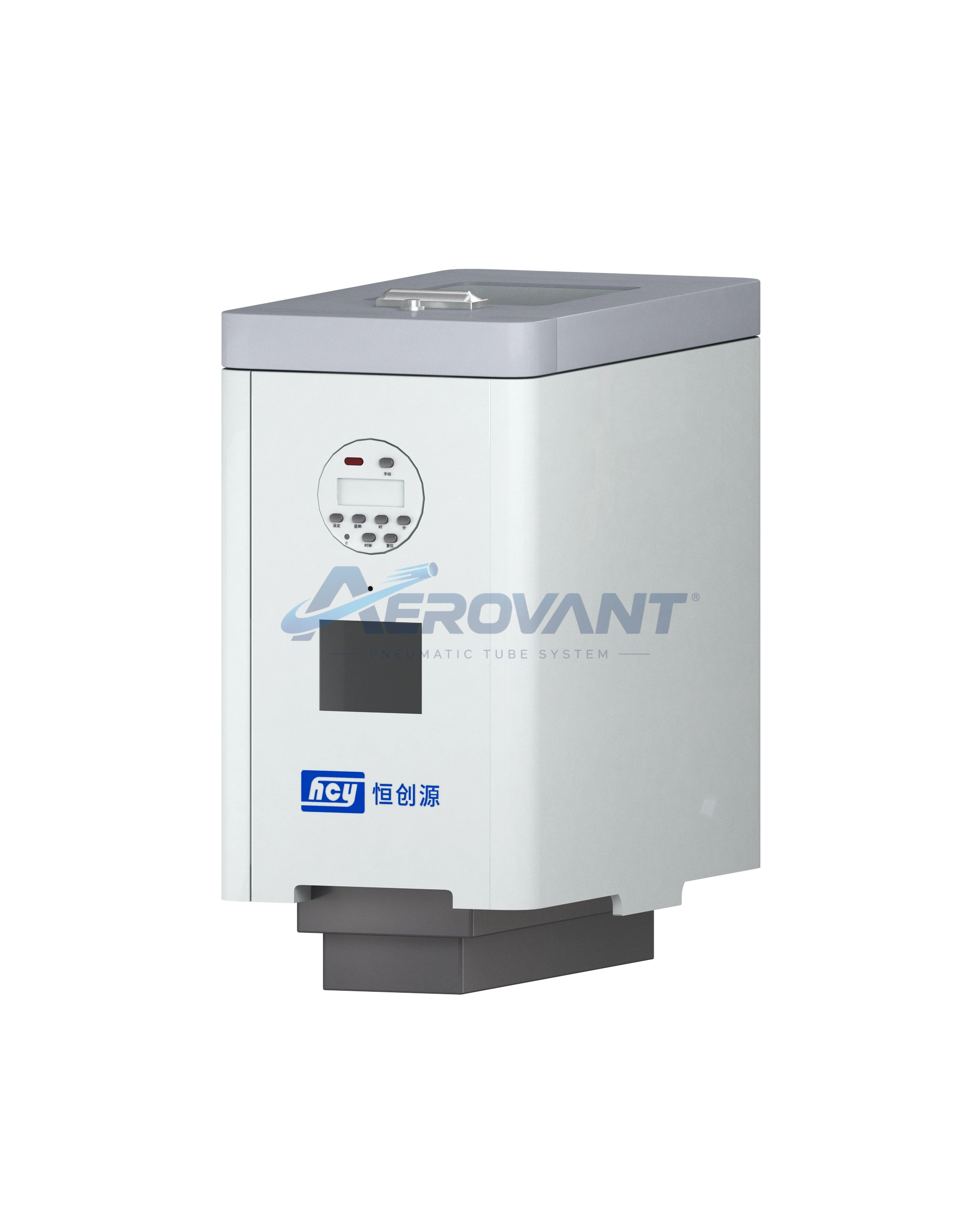
Rendering of a material transport unit.
 Enlarge ↗
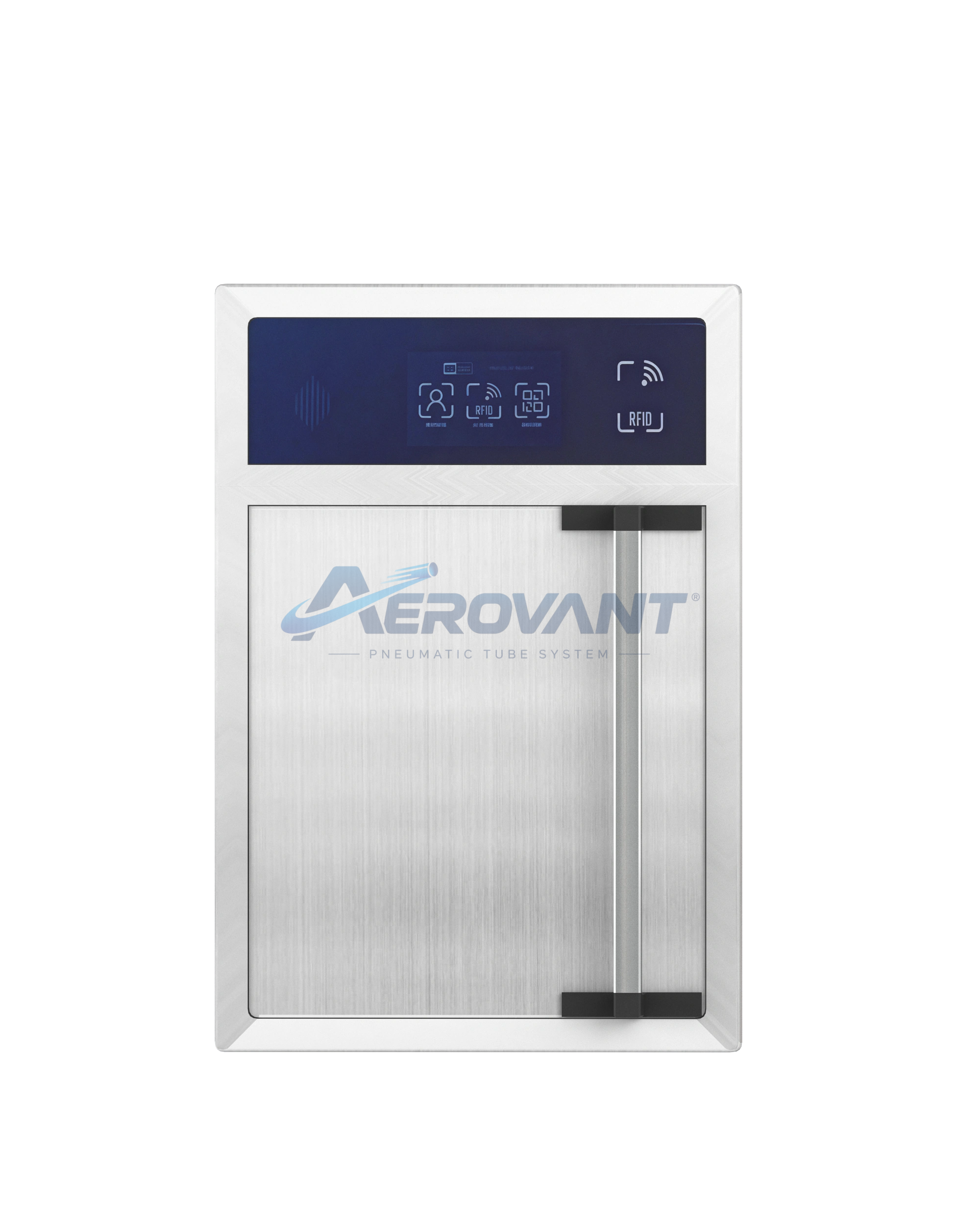
View of a terminal with an upper control panel.
 Enlarge ↗
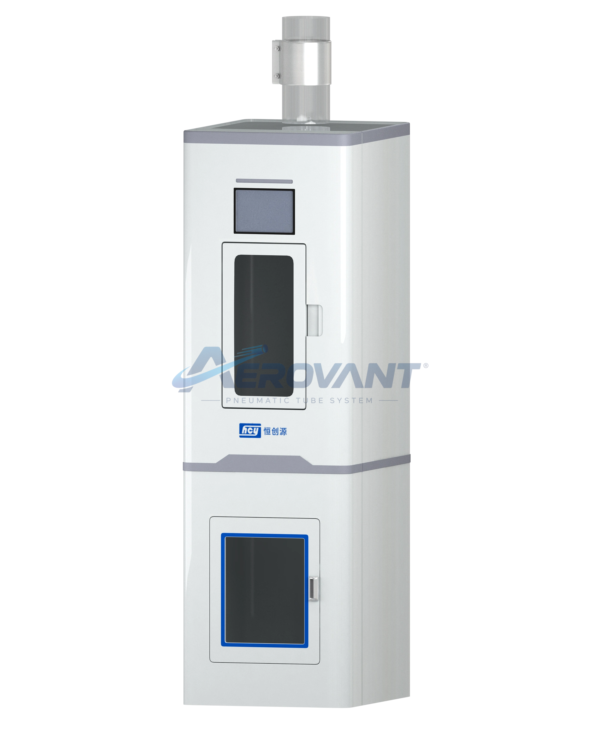
Rendering of a vertical terminal with two access areas.
 Enlarge ↗
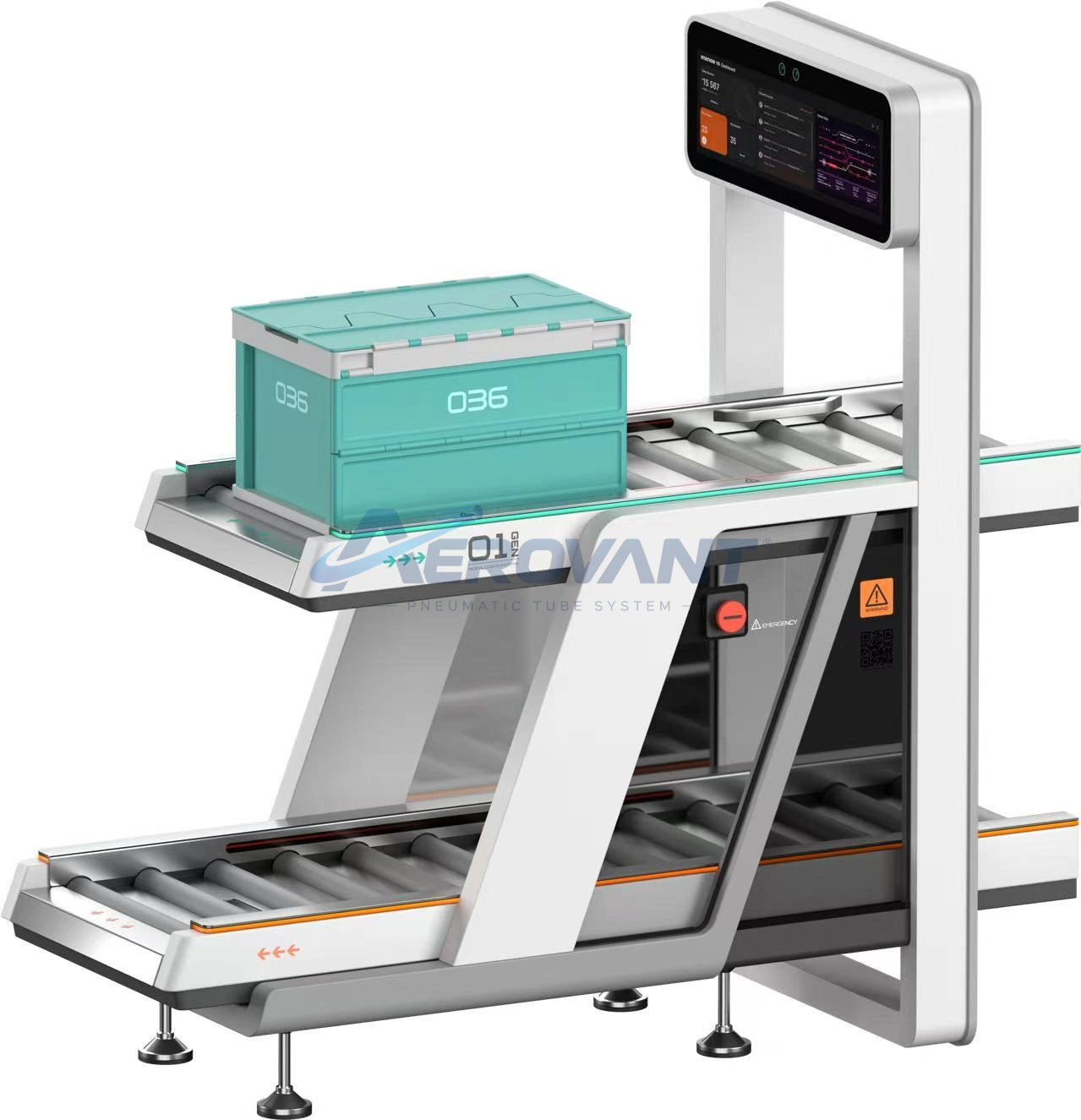
Conveyor equipment with a box and operating panel.
 Enlarge ↗
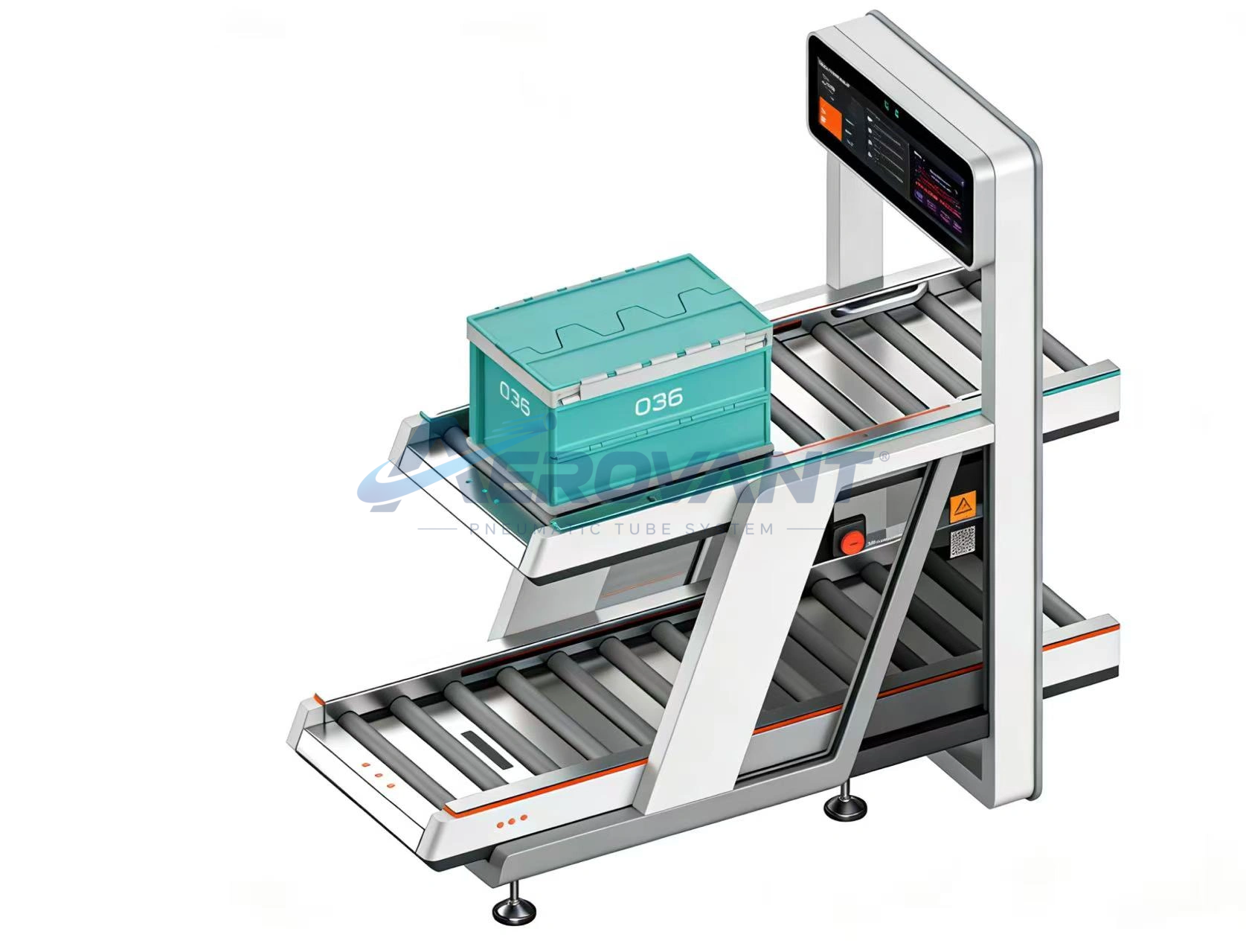
Another view of the conveyor and box equipment.
 Enlarge ↗
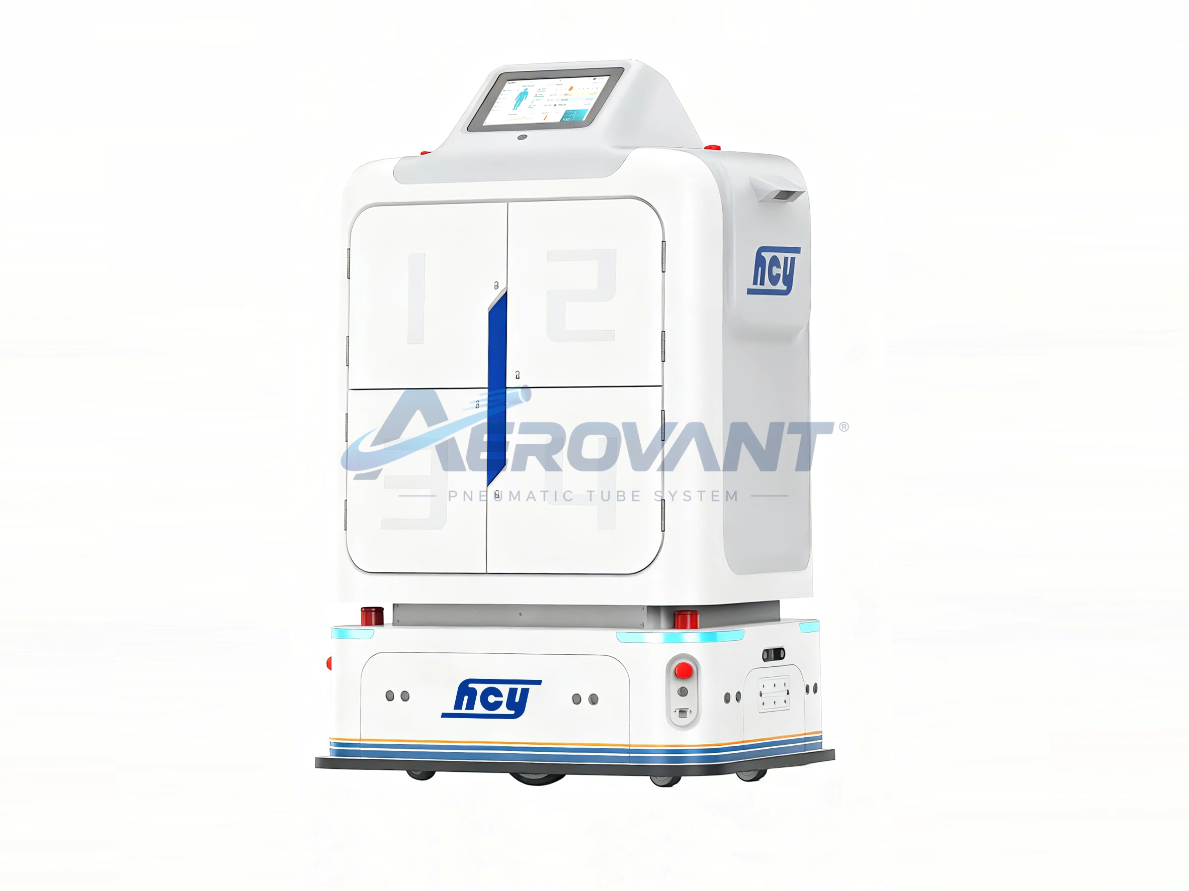
Rendering of a material transport robot.
 Enlarge ↗
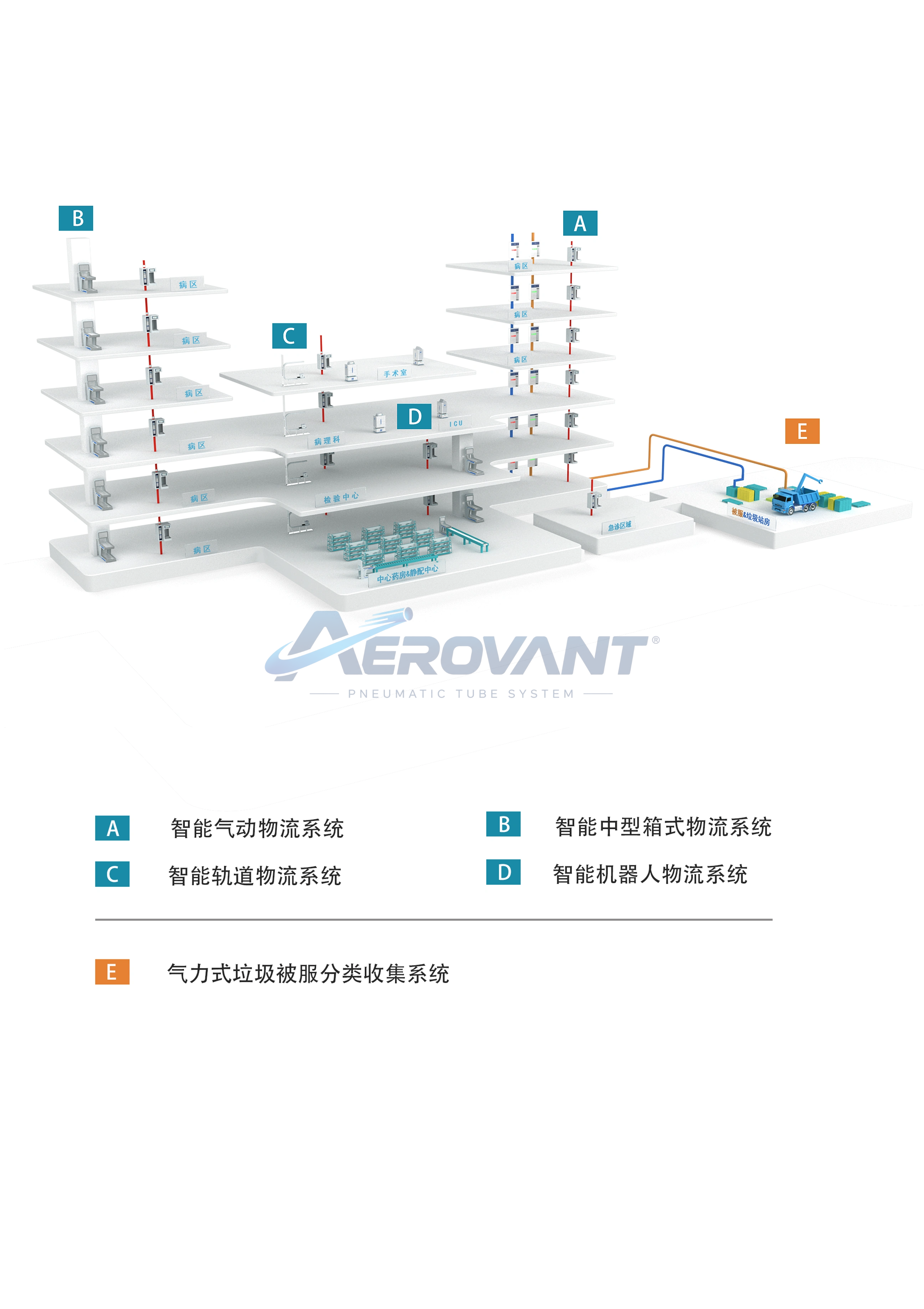
Diagram of the network and equipment within a logistics system.
 Enlarge ↗
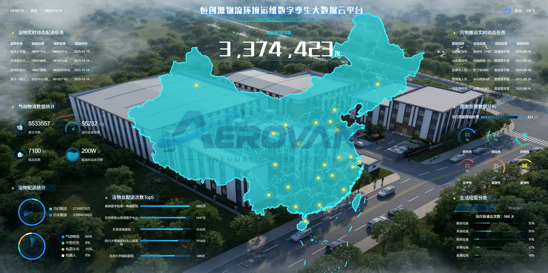
Example monitoring platform visual from the supplied asset package.
Equipment Gallery
Specimen transport system
Equipment, pipes, and installation examples supplied with the specimen system assets.
 Enlarge ↗
Photograph of specimen tubes illustrating sample transport requirements.
 Enlarge ↗
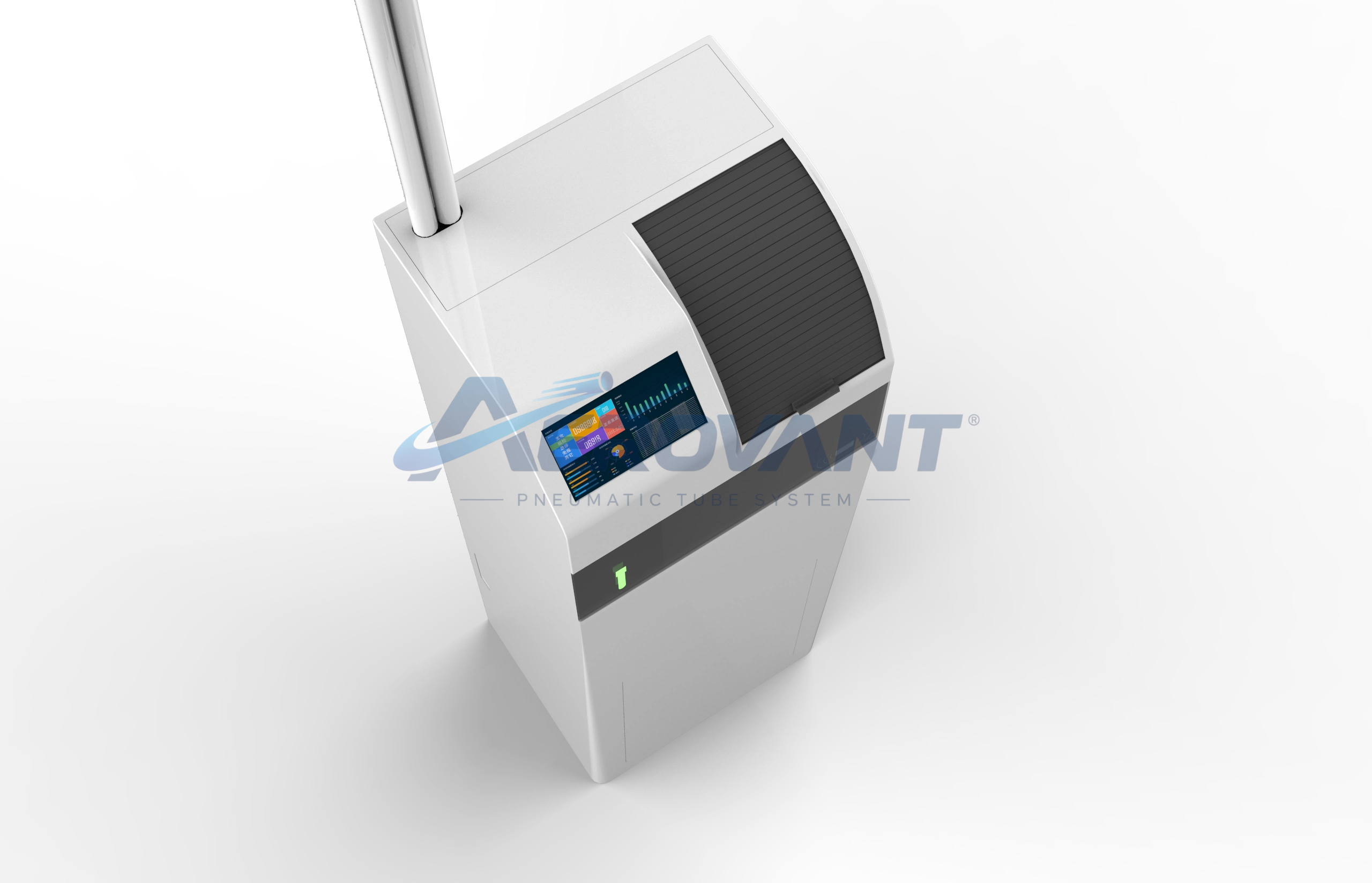
View of a terminal with its access area open.
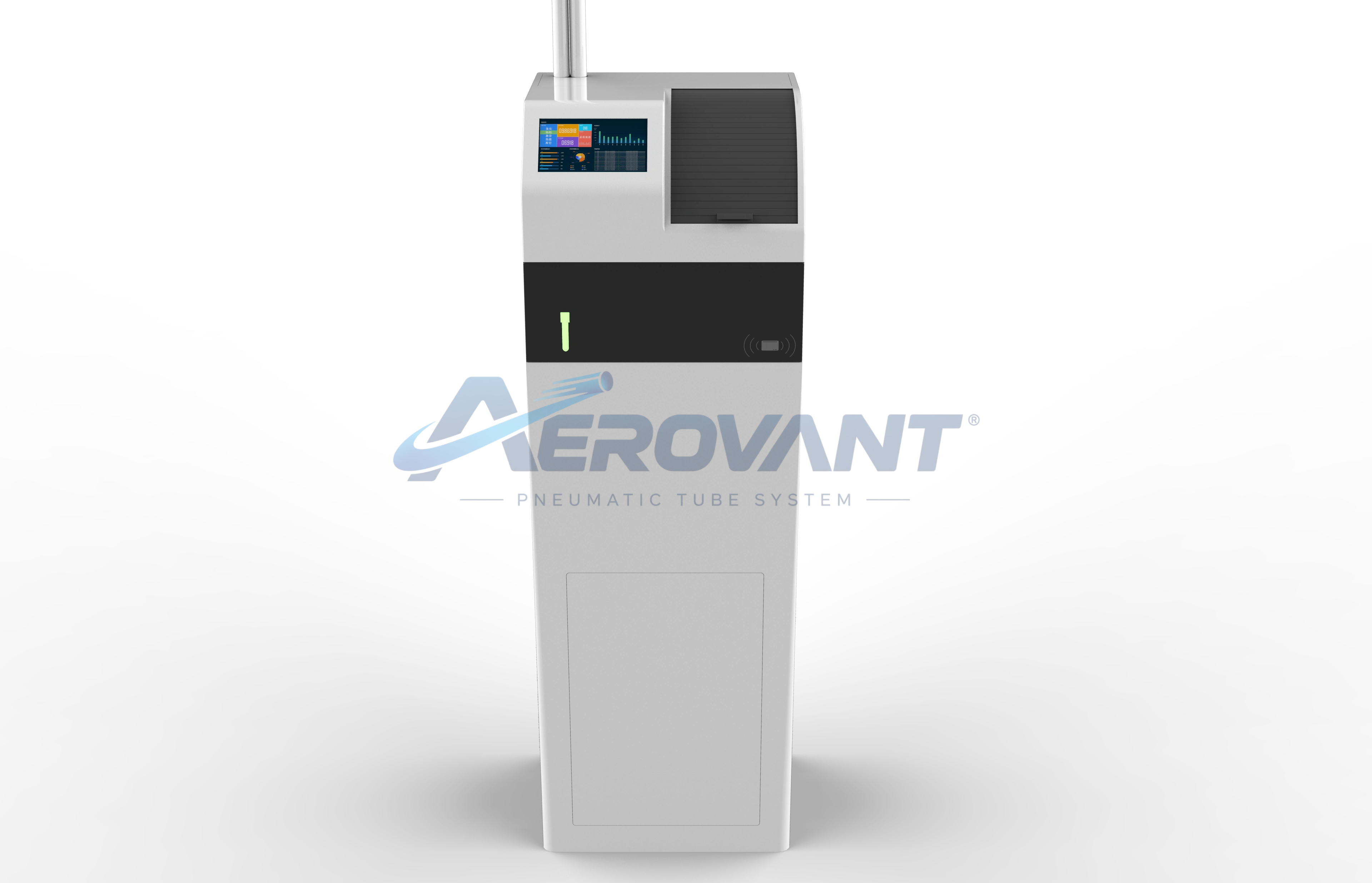 Enlarge ↗
Rendering of a specimen transport terminal.
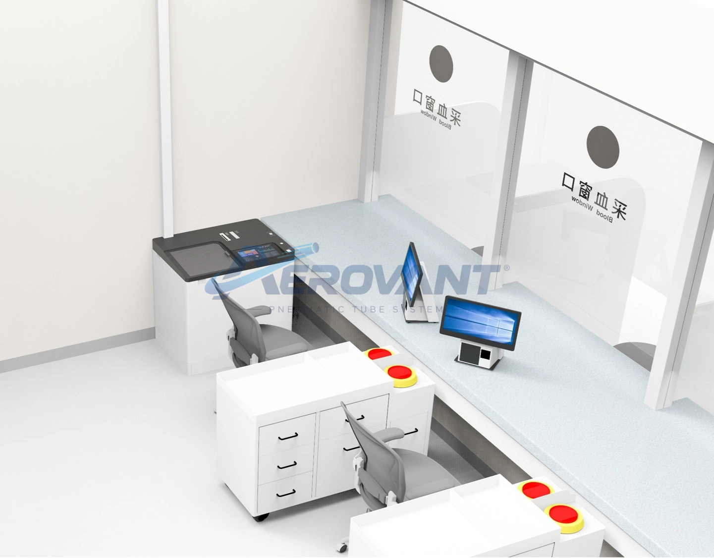 Enlarge ↗
Example equipment placement within a sample handling workflow.
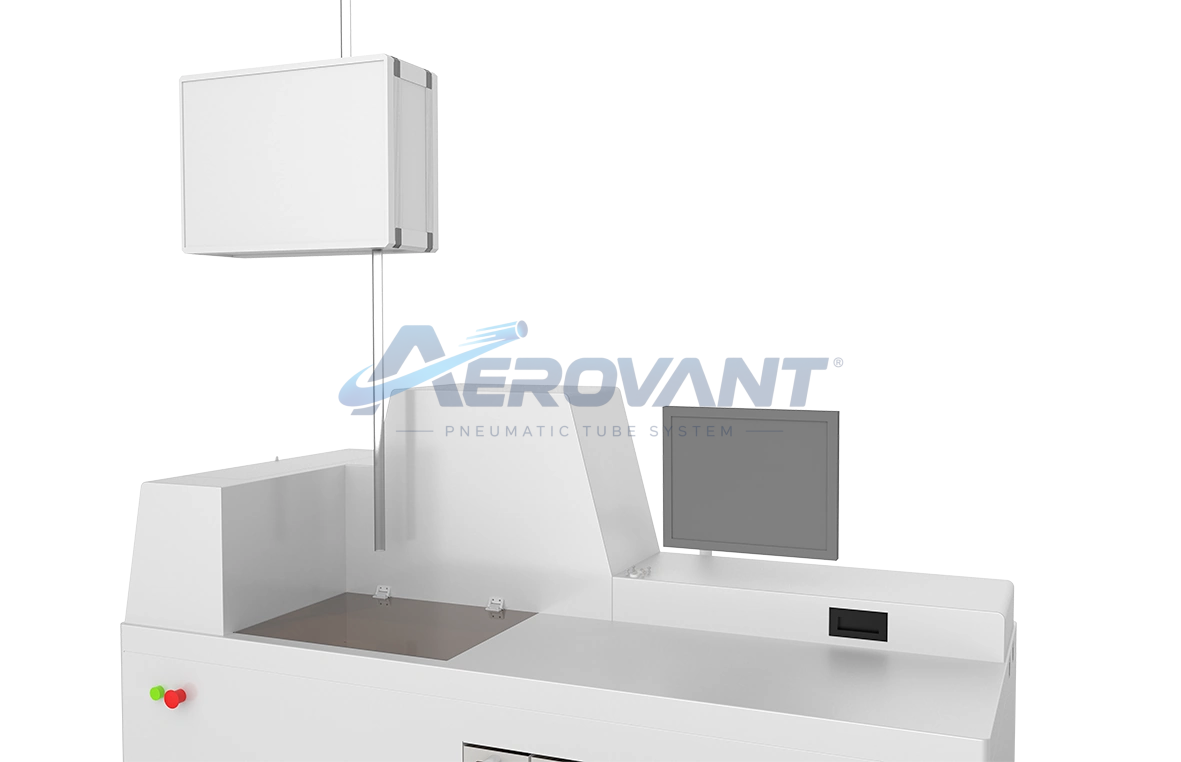 Enlarge ↗
Example equipment configuration at a receiving area.
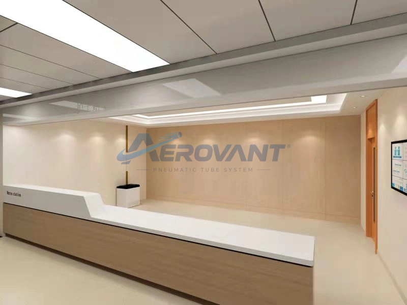 Enlarge ↗
Photograph of a service area illustrating equipment placement.
 Enlarge ↗
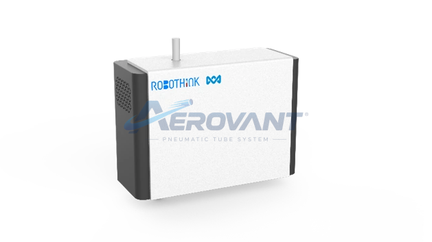
View of a receiving unit for a specimen system.
 Enlarge ↗
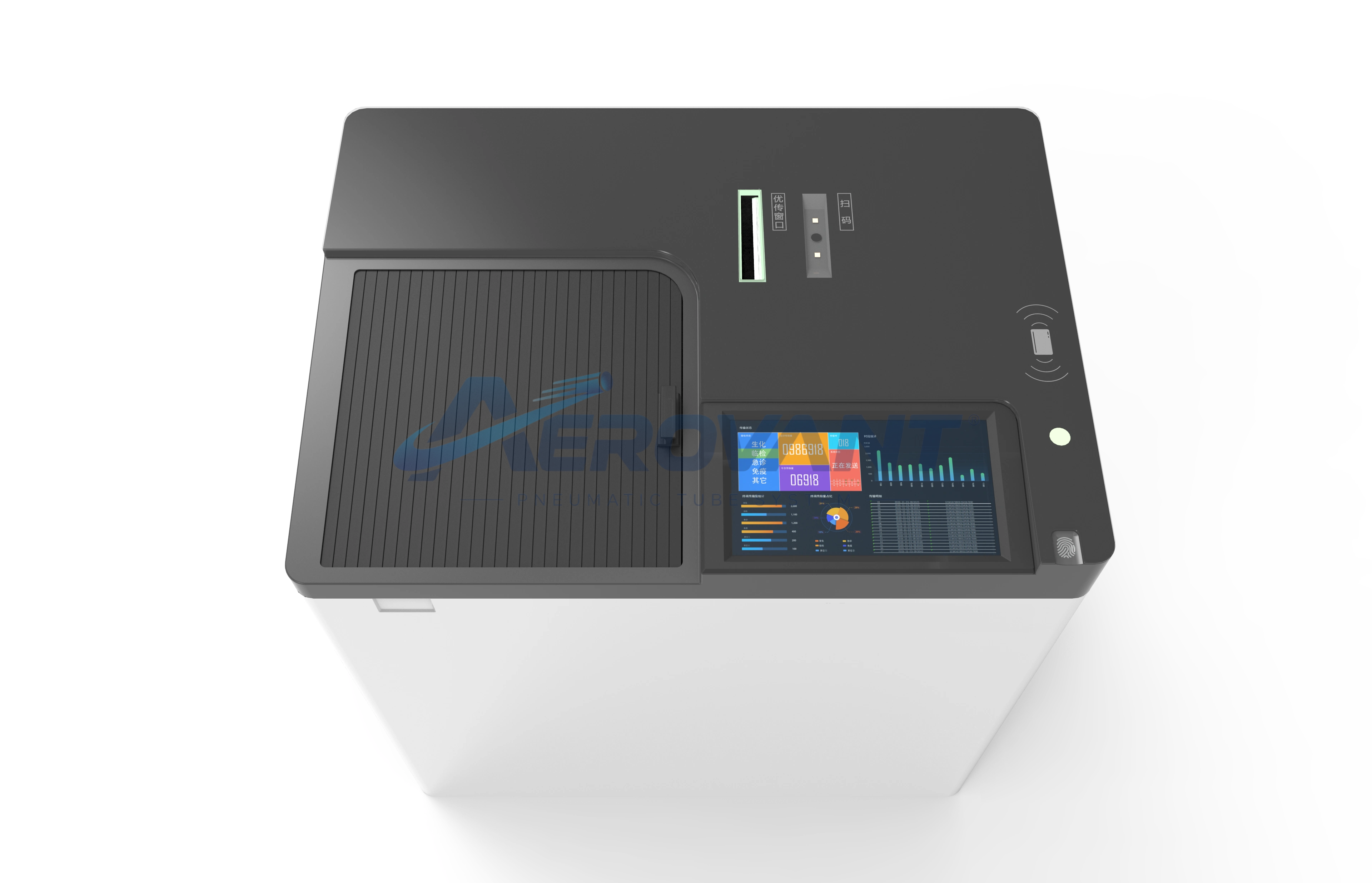
Detail of the loading area and station panel.
 Enlarge ↗
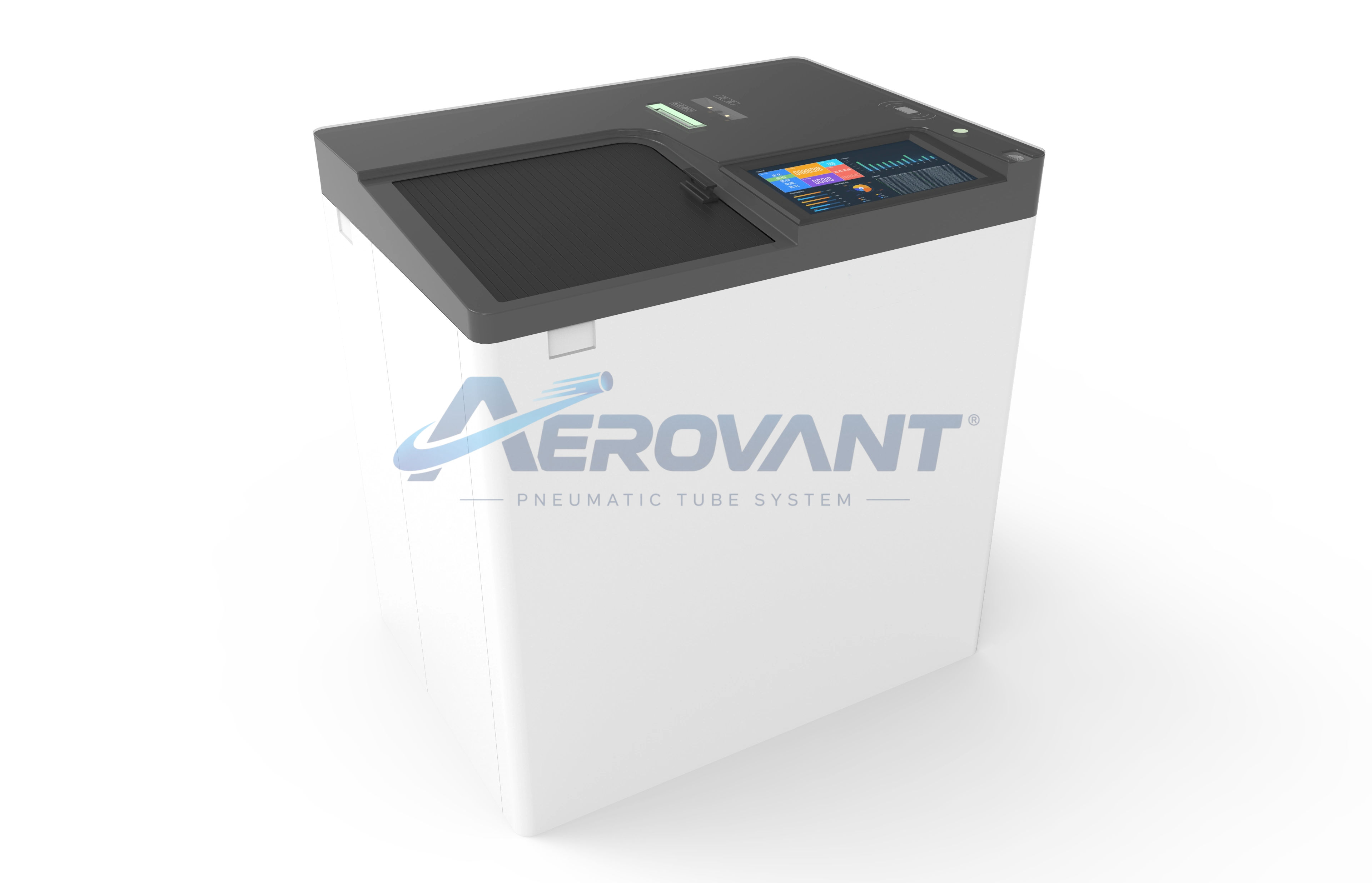
View of a specimen sending station.
 Enlarge ↗
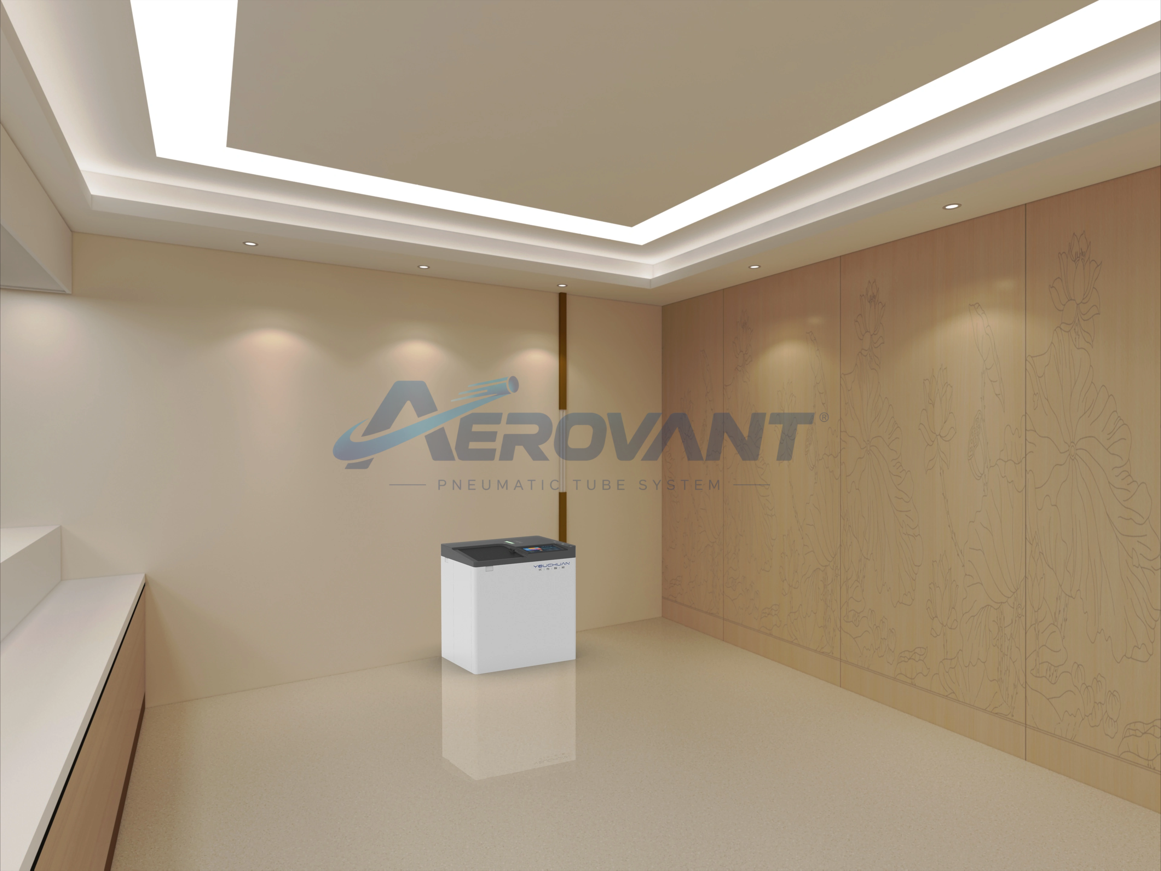
Visual of a station installed in a service room.
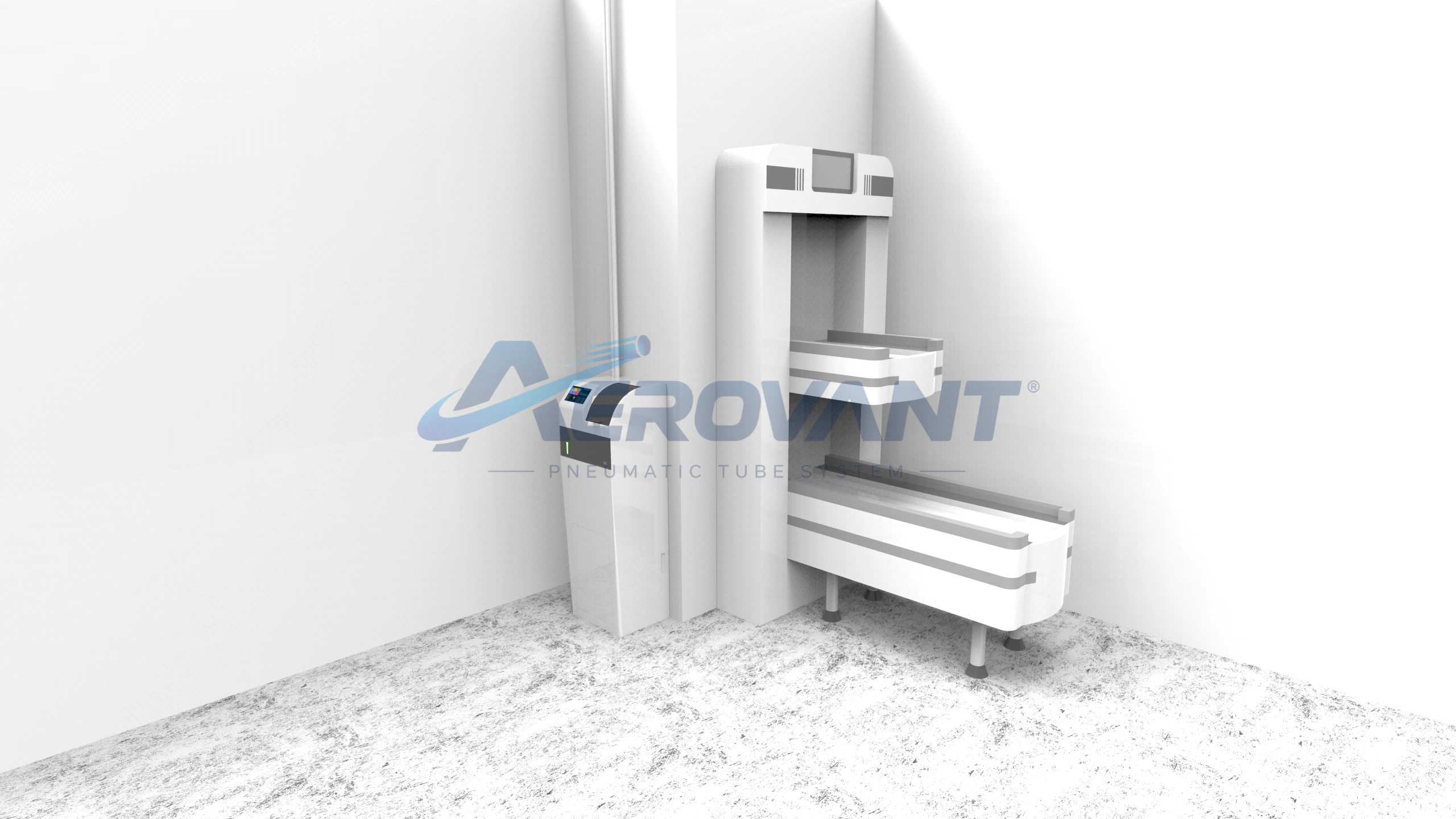 Enlarge ↗
Rendering of a terminal with multiple transfer levels.
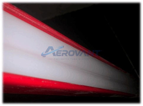 Enlarge ↗
Detailed photograph of a specimen system pipe.
Equipment Gallery
Pneumatic system
Stations, carriers, route diverters, controls, and installation examples for pneumatic systems.
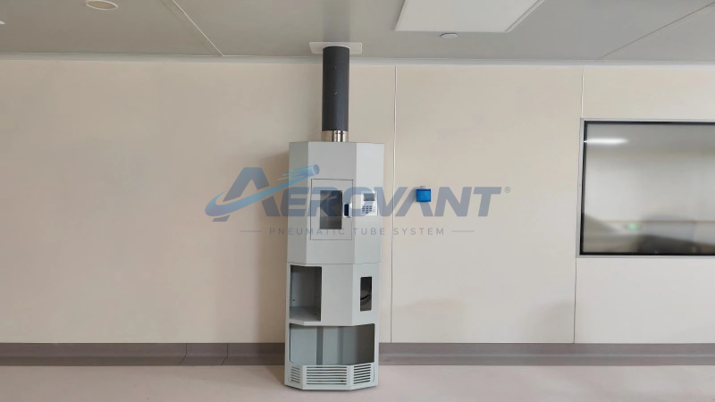 Enlarge ↗
Example pneumatic station installation inside a building.
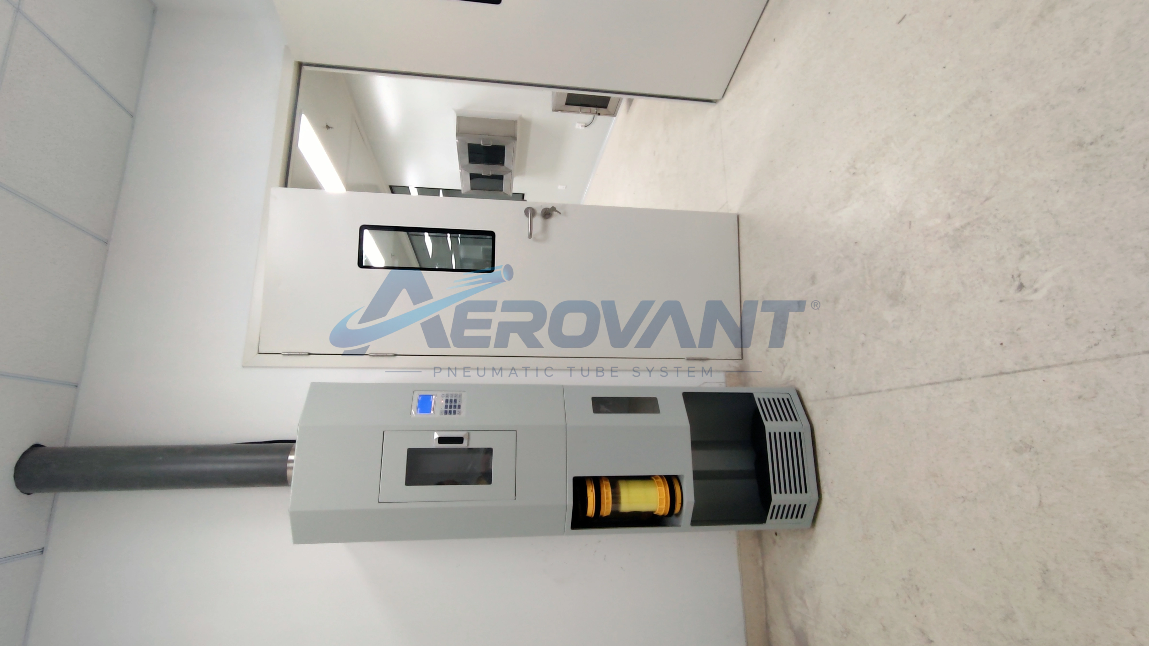 Enlarge ↗
Photograph of pneumatic equipment and piping near the ceiling.
 Enlarge ↗
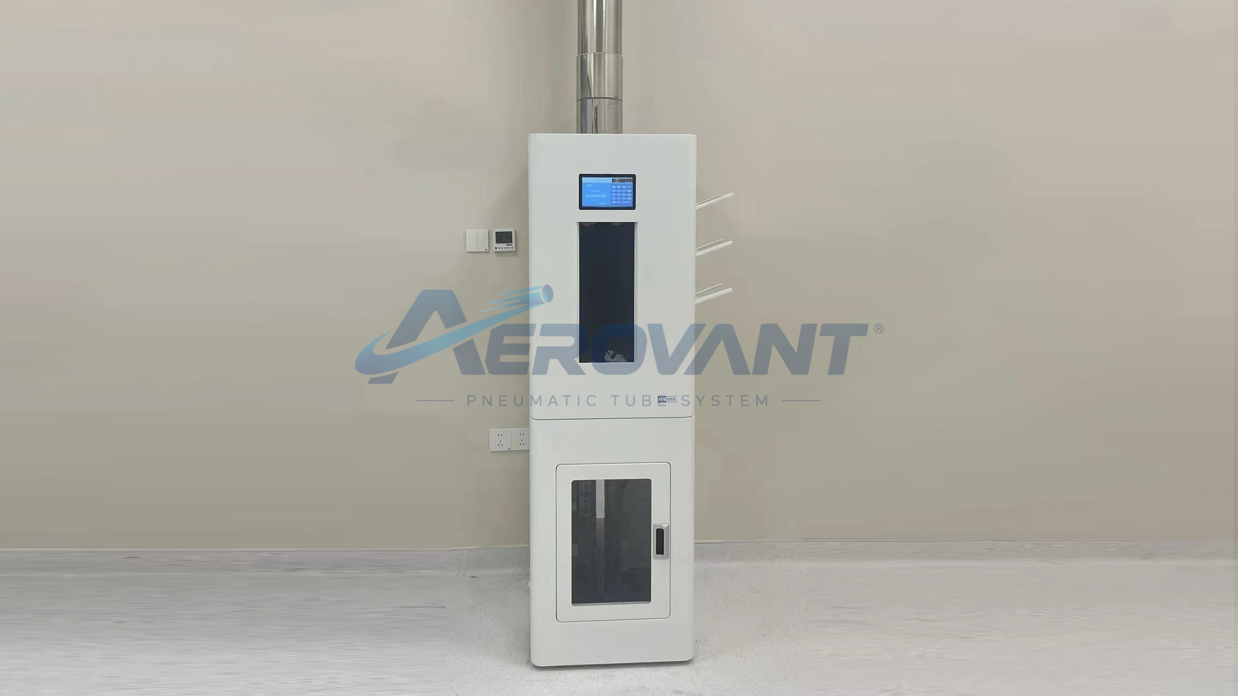
Example station equipment placement in a service area.
 Enlarge ↗
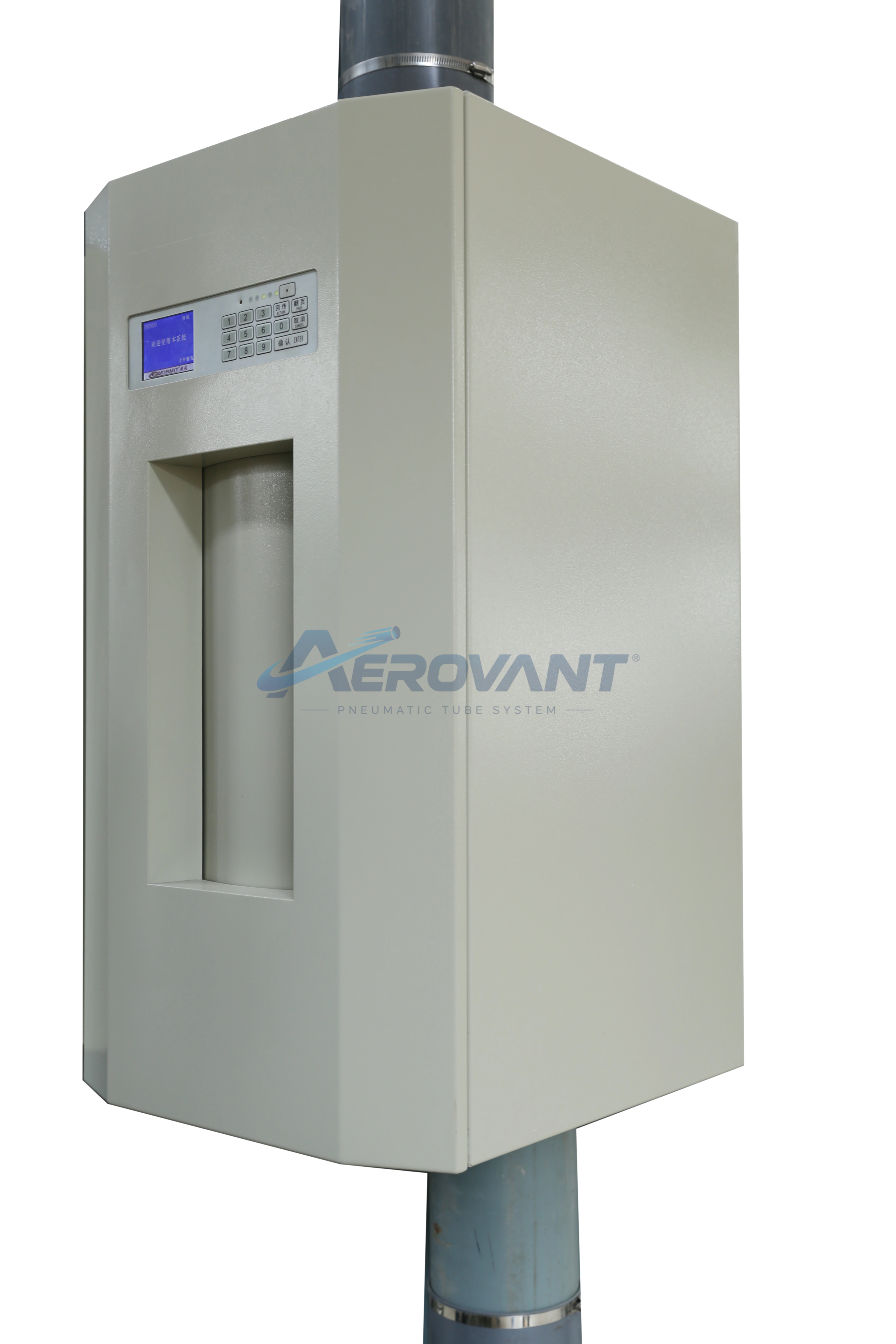
Rendering of a station with a front route connection.
 Enlarge ↗
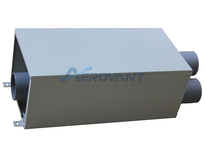
Rendering of a three-way route diverter.
 Enlarge ↗
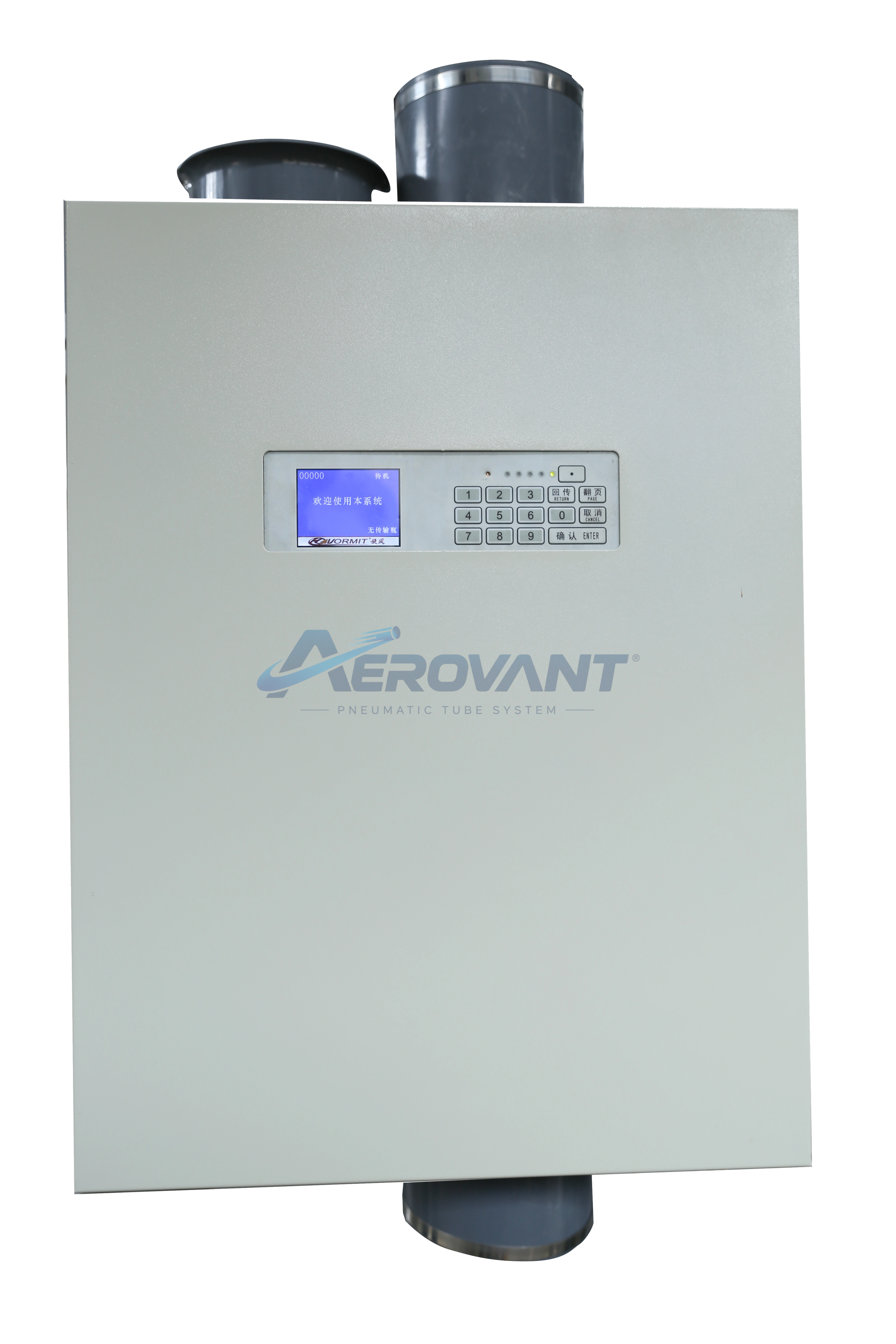
Rendering of a station with an upper connection.
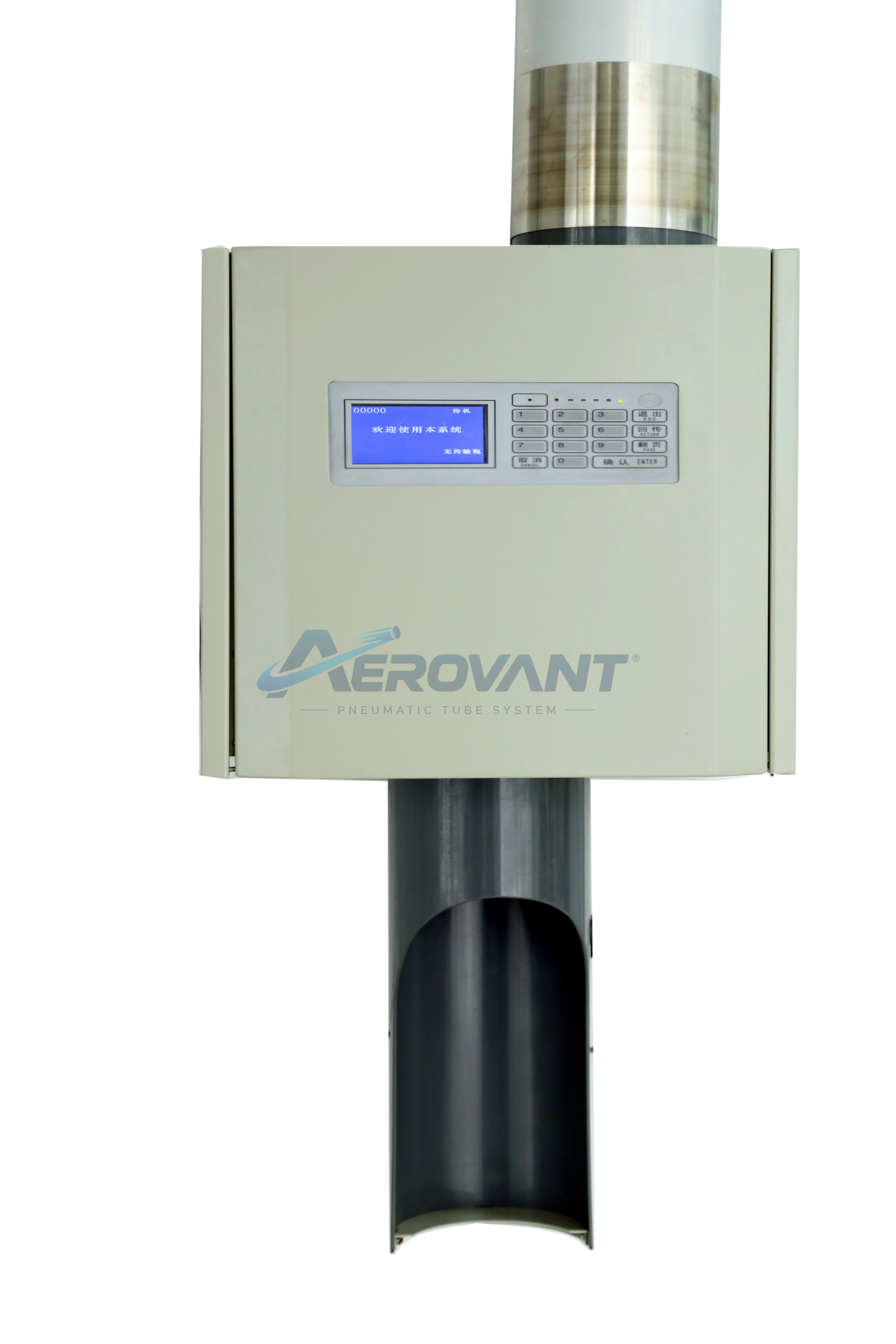 Enlarge ↗
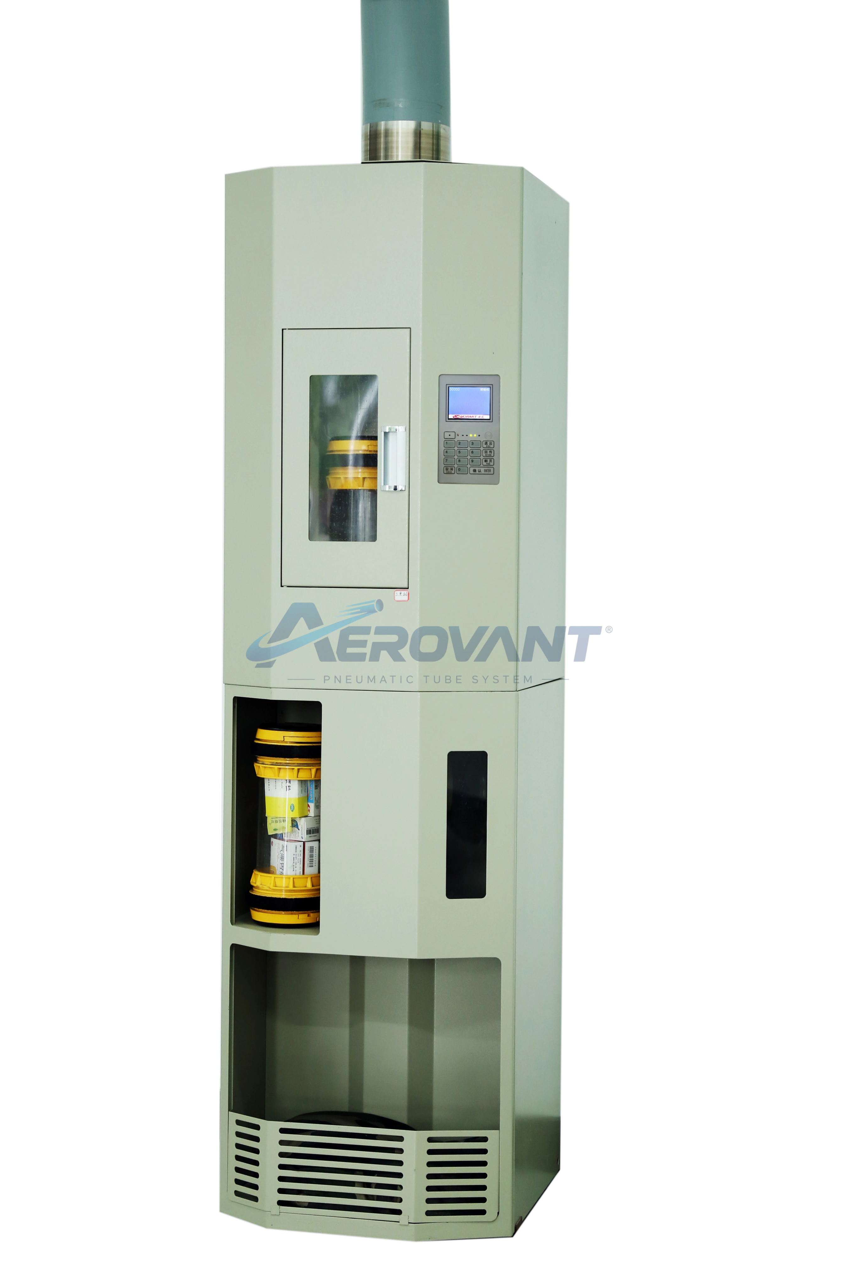
Rendering of a terminal with a lower route connection.
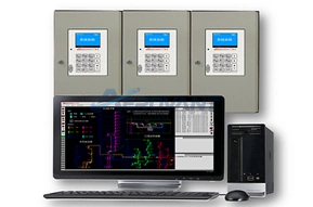 Enlarge ↗
Control and monitoring equipment for a pneumatic network.
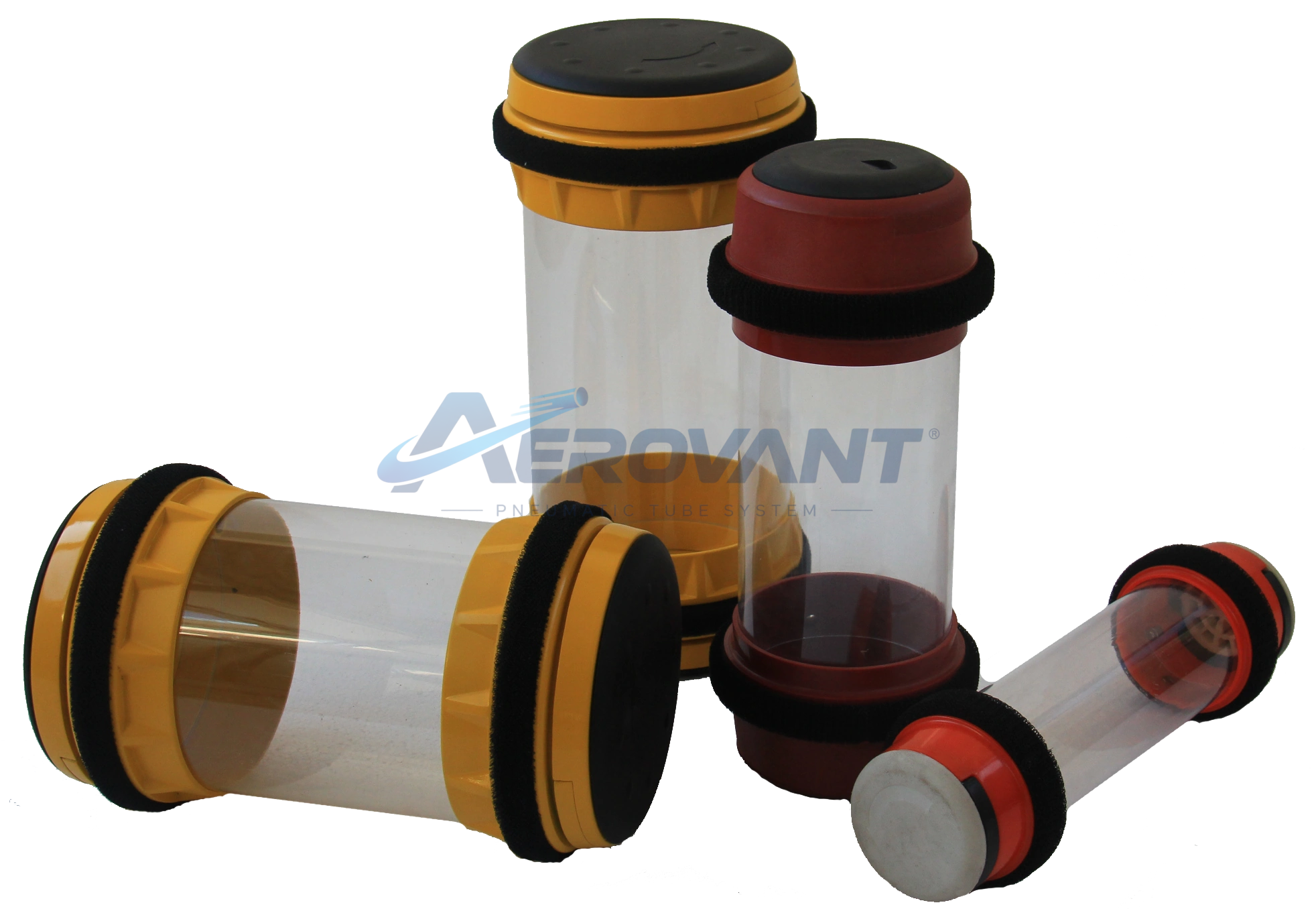 Enlarge ↗
Carriers for transport through the tube network.
 Enlarge ↗
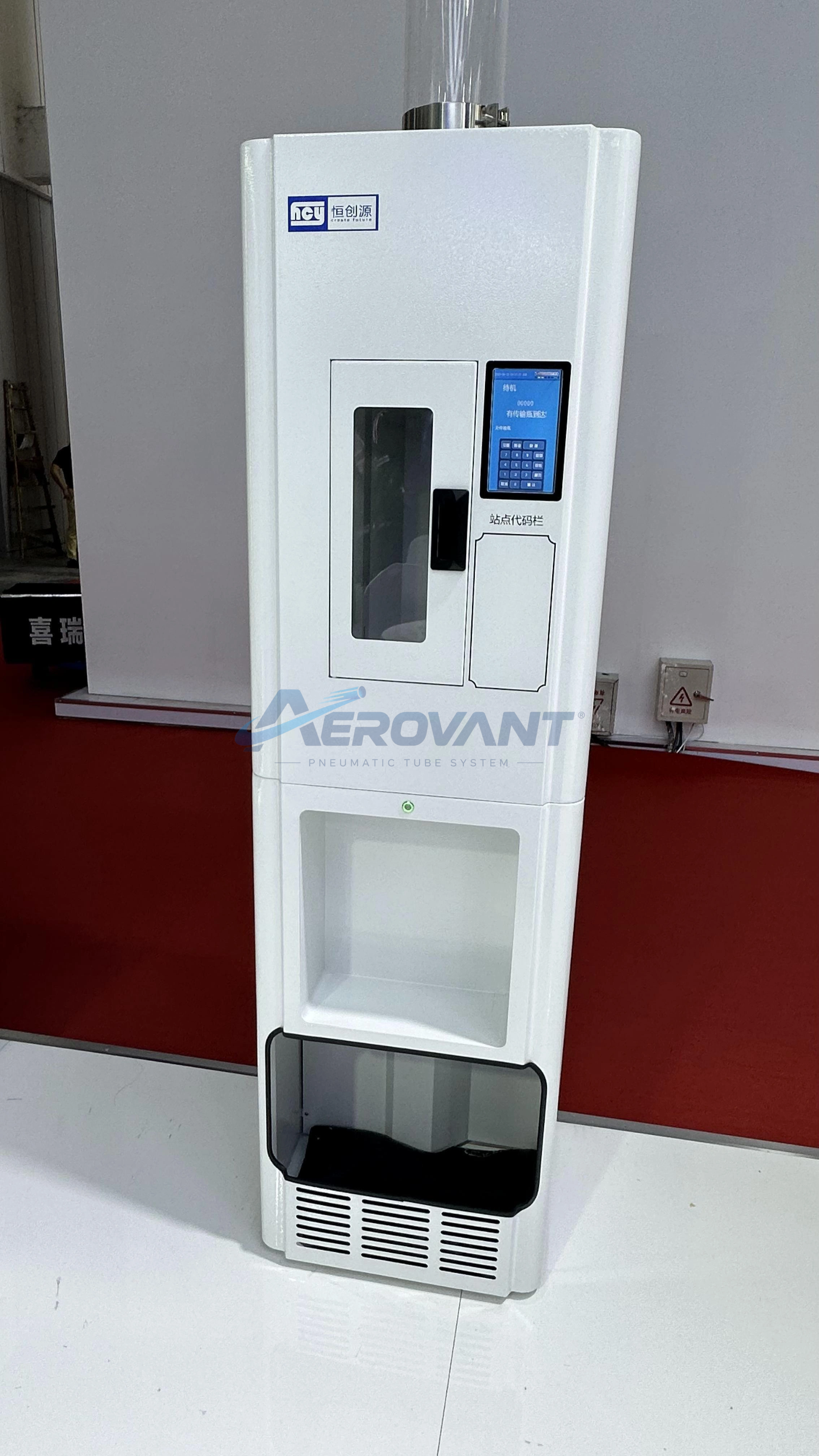
Front view of a vertical rotary station.
 Enlarge ↗
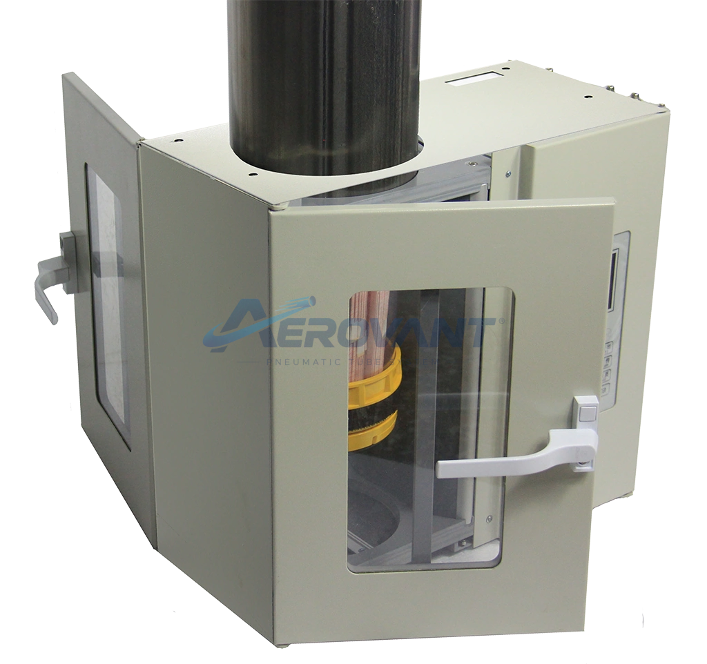
Rendering of a desktop station with two access doors.
 Enlarge ↗
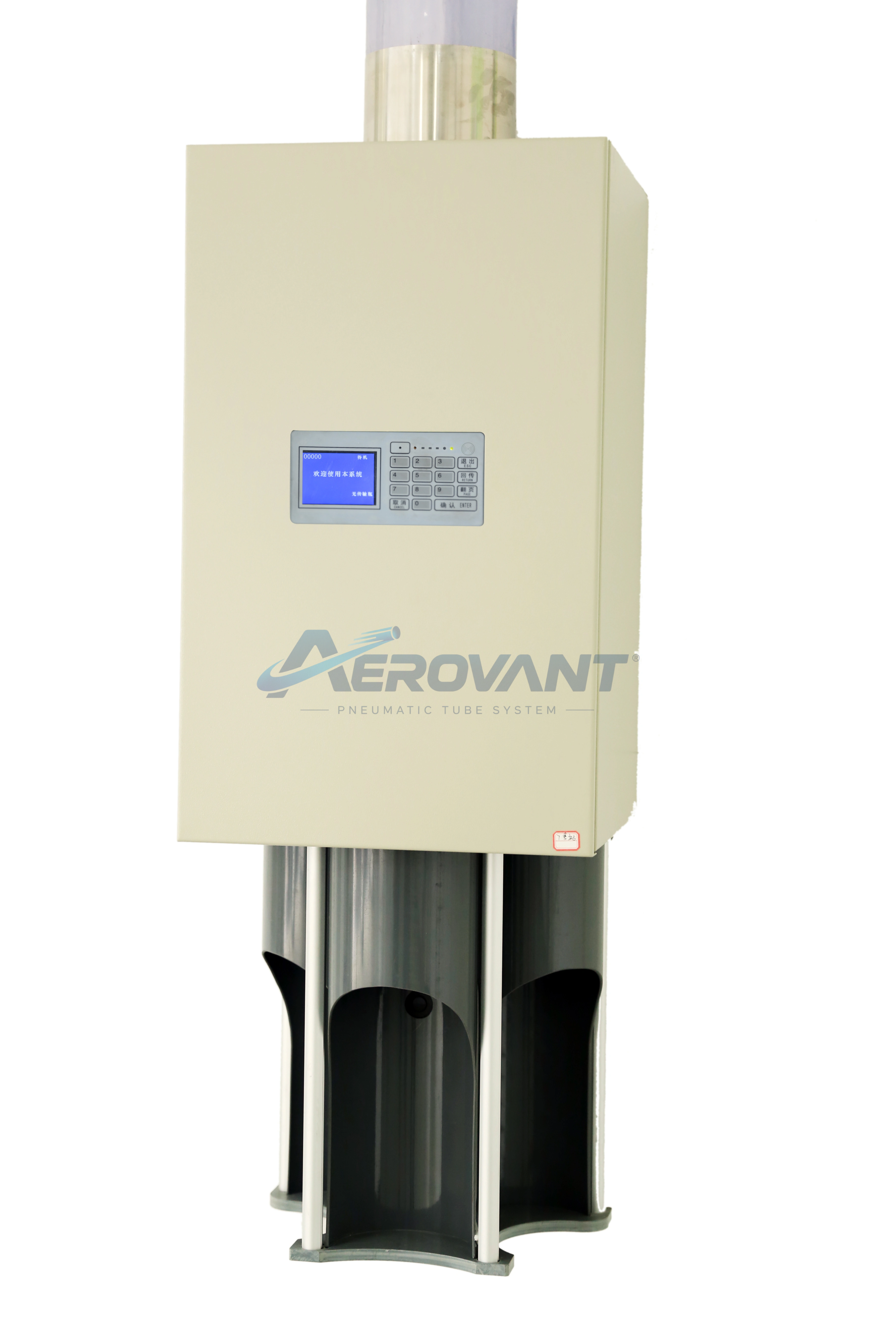
Photograph of a sending station installation.
 Enlarge ↗
Rendering of multiple sending station equipment.
 Enlarge ↗
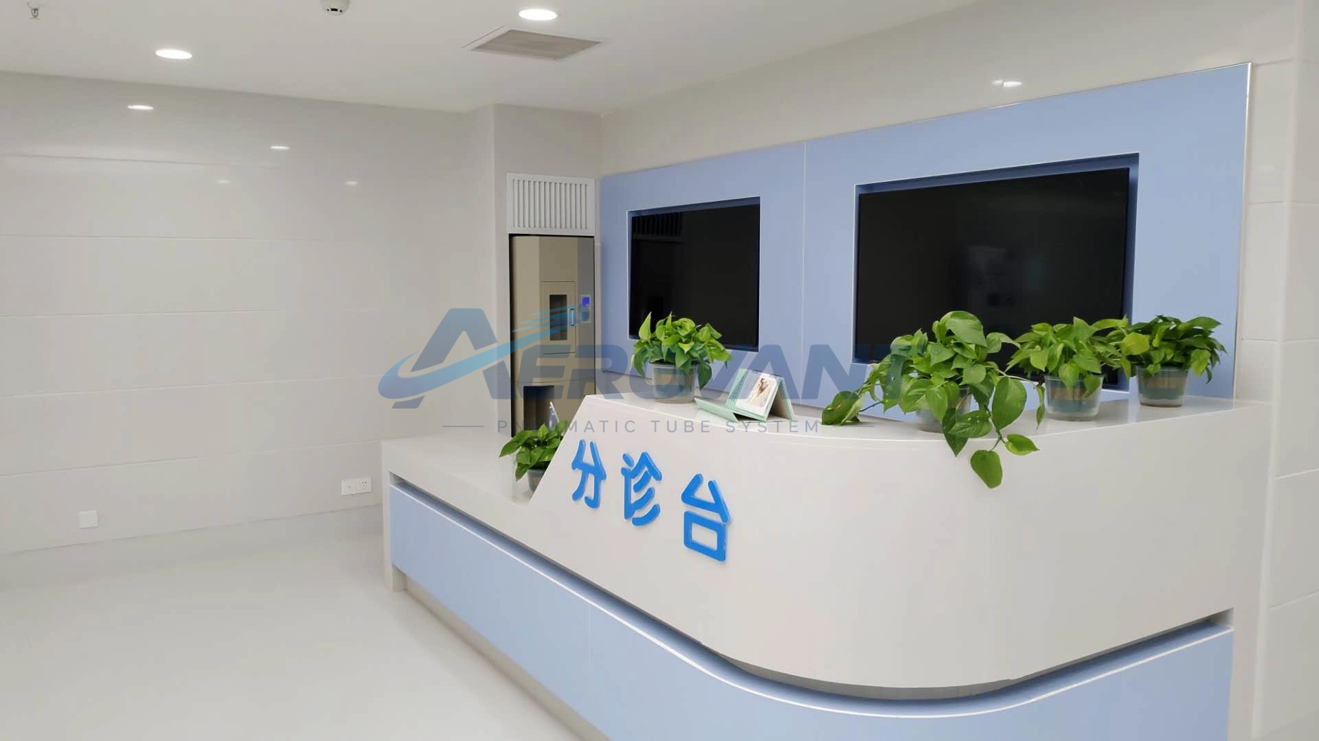
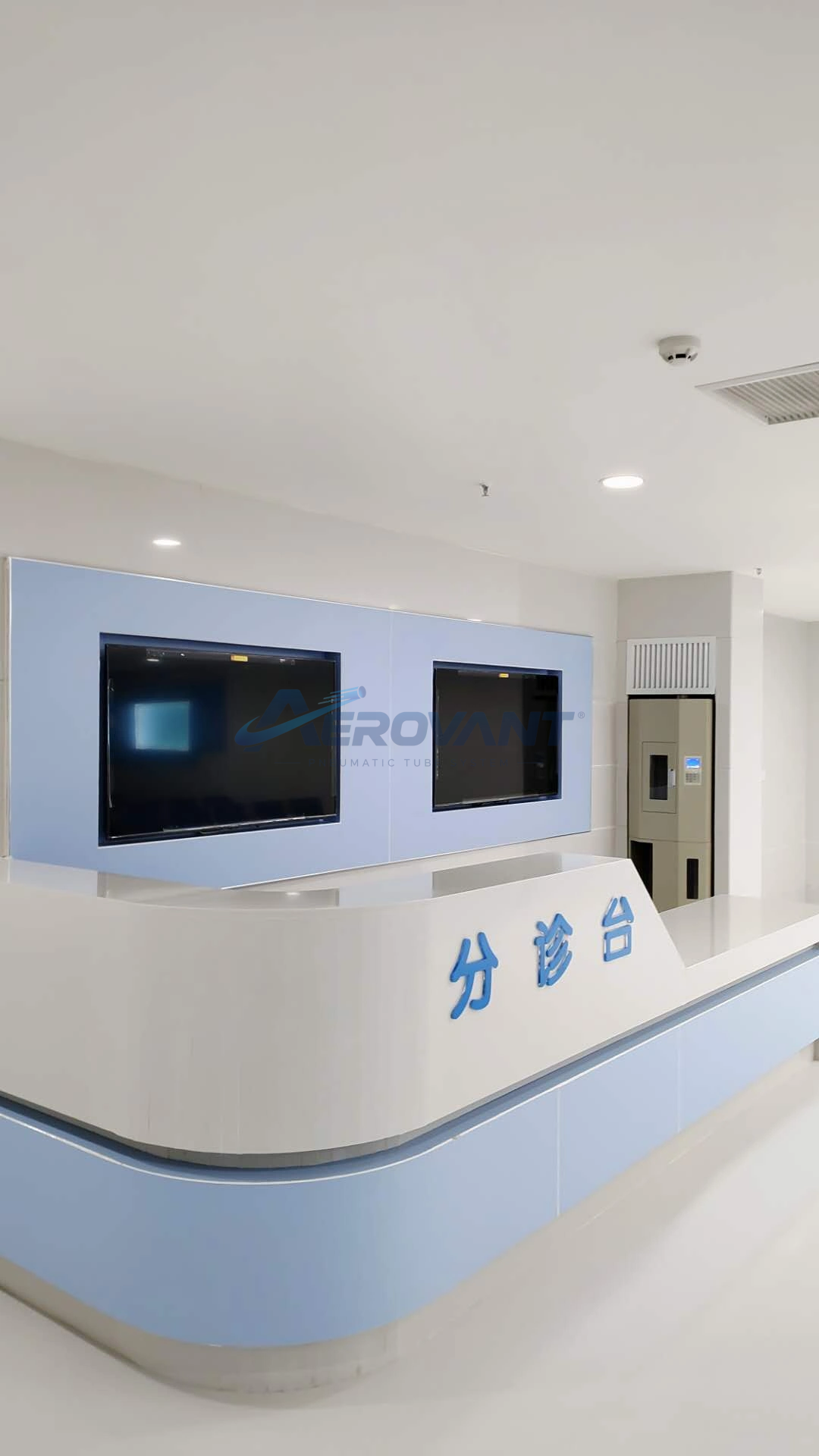
Example equipment integration with a service counter.
 Enlarge ↗
Another view of a service counter installation.
 Enlarge ↗
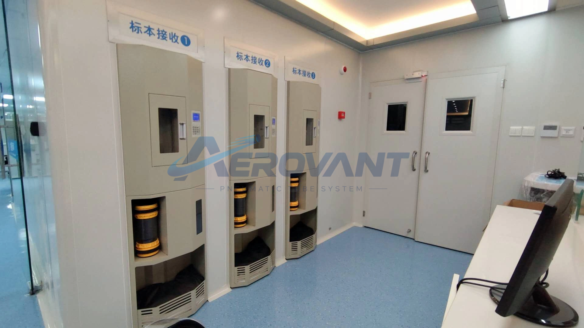
Photograph of a receiving area with several station points.
 Enlarge ↗
Air drive equipment for a pneumatic system.
Product images and system views follow the supplied source assets. Equipment configuration is selected for facility requirements.